INSTRUCTIONS-REPAIR 308868 Rev. L KEEP FOR REFERENCE. Read this and all related manuals for important warnings and instructions. First choice when quality counts.t INSTRUCTIONS GMaxr 3900, 5900, 5900HD Airless Paint Sprayers 3300 psi (227 bar, 22.
Table of Contents Warnings and Cautions . . . . . . . . . . . . . . . . . . . . . . . . . 2 Component Identification and Function . . . . . . . . . . . . 3 Maintenance . . . . . . . . . . . . . . . . . . . . . . . . . . . . . . . . . . . 4 Troubleshooting . . . . . . . . . . . . . . . . . . . . . . . . . . . . . . . . 5 Repair Bearing Housing & Connecting Rod . . . . . . . . . . . . . 7 Drive Housing . . . . . . . . . . . . . . . . . . . . . . . . . . . . . . . . 8 Pinion Assembly/Rotor/Field/Shaft/Clutch .
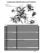
Component Identification and Function V 202 Main hose 203 Whip end hose 204 Contractor gun with RAC 5 DripLess tip guard and 517 size SwitchTip D C J H E G R K F P S A B U W T Model 232611 202 M N X L Fig.
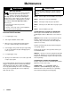
Maintenance CAUTION WARNING INJECTION HAZARD The system pressure must be manually relieved to prevent the system from starting or spraying accidentally. Fluid under high pressure can be injected through the skin and cause serious injury.
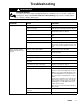
Troubleshooting WARNING INJECTION HAZARD To reduce risk of serious injury, including fluid injection or splashing in eyes or on skin, or injury from moving parts, always follow Pressure Relief Procedure Warning, page 4, before checking, adjusting, cleaning or shutting down sprayer. Check everything in chart before disassembling sprayer. PROBLEM CAUSE SOLUTION Engine won’t start Engine switch is OFF Turn engine switch ON Engine is out of gas Refill gas tank. Honda Engines Owner’s Manual.
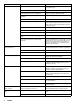
PROBLEM CAUSE SOLUTION Pump output is low Strainer (31) is clogged Clean strainer. Sprayer 232627 strainer is for use in paint only. Piston ball (25) is not seating Service piston ball. Manual 308798. Piston packings are worn or damaged Replace packings. Manual 308798. O-ring (227) in displacement pump is worn or damaged Replace o-ring. Manual 308798. Intake valve ball is not seating properly Clean intake valve. Manual 308798. Intake valve ball is packed with material Clean intake valve.
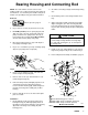
Bearing Housing and Connecting Rod NOTE: The item numbers referenced are for the Hi-Boy models. The Lo-Boy models may have different item numbers. Use the Hi-Boy item number and part to find the corresponding Lo-Boy part and item number. Removal 1. Relieve pressure; page 4. 2. Fig. 3. Remove screws (14) and front cover (23). 3. For Hi-Boy models; remove spring clip (32) and drain hose (54). Unscrew suction tube (30) from pump, hold wrench on pump intake valve (A) to keep pump from loosening.
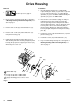
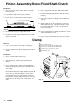
Drive Housing Installation Removal 1. 1. Liberally apply bearing grease (supplied with replacement gear cluster) to gear cluster (18) and to areas called out by note 3. Use full 0.62 pint (0.29 liter) of grease for GMax 3900 and 0.68 pint (0.32 liter) of grease for GMax 5900. Relieve pressure; page 4. 2. Fig. 4. Remove bearing housing. Do 1. through 8. of Bearing Housing and Connecting Rod procedure on page 7. 2.
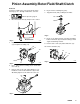
Pinion Assembly/Rotor/Field/Shaft/Clutch Removal 6. Fig. 8. Remove retaining ring (19e). If pinion assembly (19) is not removed from clutch housing (5), do 1. through 4. Otherwise, start at 5. 1. 7. Tap pinion shaft (19d) out with plastic mallet. Relieve pressure; page 4. 19e 2. Disconnect field cable (X) from pressure control. 19d X 8703A Fig. 8 Bottom View 8699A Fig. 5 3. Fig. 6. Remove five screws (10) and lockwashers (17) and pinion assembly (19). 8. Fig.9.
Pinion Assembly/Rotor/Field/Shaft/Clutch Installation 1. Fig. 10. Lay two stacks of two dimes on smooth bench surface. 7. Install retaining ring (Z) with beveled side facing field (Y). 2. Lay armature (4a) on two stacks of dimes. 3. Press center of clutch down on bench surface. 4a 6. Fig. 8. Tap pinion shaft (A) in with plastic mallet. 8. Fig. 7. Place pinion assembly on bench with rotor side up. 0.12 ±.01 in. (3.0 ±.25 mm) 8705A Fig. 10 9. Apply locktite to screws.
Clutch Housing Removal 1. Fig. 12. Remove four capscrews (75) and lockwashers (77) which hold clutch housing (5) to engine. 5 7 2. Remove screw (15) from under mounting plate (D). 3. Remove engine key (7). 4. Pull off clutch housing (5). Installation 77 1. Fig. 12. Push on clutch housing (5). 75 2. Install four capscrews (75) and lockwashers (77) and secure clutch housing (5) to engine. Torque to 200 in-lb (22.6 NSm). D 15 3. Install capscrew (15) from beneath mounting plate (D).
On/Off Switch Removal Installation 1. 1. Install new ON/OFF switch (309) so tabs of switch snap into place on inside of pressure control housing. Relieve pressure; page 4. 2. Fig. 15. Remove five screws (307) and cover (322). 3. Disconnect two wires (A) from ON/OFF switch (309). 4. Press in on two retaining tabs on each side of ON/OFF switch (309) and remove switch. 3. Install pressure control cover (322) with five screws (307). 313 310 1 309 2. Connect two wires (A) to ON/OFF switch.
Pressure Control Control Board Installation Removal 1. Relieve pressure; page 4. 2. Fig. 15. Remove five screws (307) and cover (322). When installing replacement control board, follow instructions with control board to set model type. 1. Fig. 15. Install green ground wire and control board (302) with five screws (303). 3. Fig. 22. Disconnect at control board (302): D Four clutch leads: two violet and two black. 2. Fig. 22. Connect to control board (302): D Lead (D) from potentiometer.
Pressure Control Control Board Diagnostics 1. Fig. 15. Remove five screws (307) and cover (322). 2. Start sprayer. 3. Turn ON/OFF switch ON. 4. Observe LED operation and reference following table: LED BLINKS SPRAYER OPERATION Two times repeatedly Sprayer shuts down and LED contin- Run away pressure. Pressure greater than ues to blink two times repeatedly 4500 psi (310 bar, 31 MPa). 1. Check pressure transducer connection at control board 2. Replace pressure transducer 3.
Displacement Pump Removal 1. Flush pump. 5. Fig. 17. Use screwdriver: push retaining spring up and push out pin (29). 29 2. Relieve pressure; page 4. 3. Fig. 16. Cycle pump with piston rod (222) in its lowest position. 4. Fig. 16. Remove suction tube (30) and hose (33). 7675B Fig. 17 6. Fig. 18. Loosen locknut by hitting firmly with a 20 oz (maximum) hammer. Unscrew pump. 222 33 30 Fig. 16 7672B 7673B Fig. 18 Repair See manual 308798 for pump repair instructions.
Parts Drawing – GMax 3900, 5900, 5900HD Hi-Boy Sprayers Models 232610, 232620 and 232627 DETAIL A Ref 11 40 45 37 38 39 1 Label 2 See page 18 for the parts. 3 See manual 308798 for the parts. 4 See page 22 for the parts.
Parts List – GMax 3900, 5900, 5900HD Hi-Boy Sprayers Models 232610, 232620 and 232627* Ref No. Part No.
Parts List & Drawing – Pinion Assembly Ref No. 19 and 20 Ref No. 19: Pinion Housing Assembly 241108 for GMax 3900; Pinion Housing Assembly 241112 for GMax 5900 Ref No. 20: Drive Housing Assembly 241007 for GMax 3900; Drive Housing Assembly 241011 for GMax 5900 Ref No. Ref No. 19 19b 19d* Part No.
Notes 308868 19
Parts Drawing – GMax 3900 and GMax 5900 Lo-Boy Sprayers Models 232612 and 232622 DETAIL A Ref 11 Label 2 See page 18 for the parts. 3 See manual 308798 for the parts. 4 See page 22 for the parts.
Parts List – GMax 3900 and GMax 5900 Lo–Boy Sprayers Models 232612 and 232622 Ref No. Part No.
Parts Drawing – Sprayer GMax 3900 and 5900 Sprayers Models 232610 through 232613 Models 232620 through 232623; 232627 and 232628 307 301 318f 314 313 304 305 310 309 308 318e 312 304 319 321 302 318d 303 320 318b 315 318c 318z 306 311 318aa 323 310 318a 305 322 318g 307 318h 318m 318n 318l 318j 318k 8716A 22 308868
Parts List – Sprayer Models 232610 through 232613; 232620 through 232623; 232627 and 232628 REF REF NO. PART NO. DESCRIPTION 301 302 303 304 305 306 307 308 309 310 311 312 313 314 315 318 318a 318b 318c 318d 318e 193653 241093 111839 240776 193497 193652 114631 193052 114277 241443 193657 193654 114273 193072 114629 PLATE, control BOARD, PC SCREW, mch pan, 6–32 x 1/2 in. HARNESS, wiring.
Parts List & Drawing – Complete Sprayers Models 232611, 232613, 232621, 232623, 232628 GMax 3900, 5900, 5900HD Airless Paint Sprayers Includes items 201 to 204 Ref No. Part No. Description 201 232611 GM3900 Hi-Boy Sprayer 1 See parts list on page 16 GM5900 Hi-Boy Sprayer 1 See parts list on page 16 GM5900HD Hi-Boy Sprayer 1 See parts list on page 16 GM3900 Lo-Boy Sprayer 1 See parts list on page 21 GM5900 Lo-Boy Sprayer 1 See parts list on page 21 HOSE, grounded, nylon; 1/4 in.
Technical Data Honda GX120 Engine Power Rating @ 3700 rpm ANSI . . . . . . . . . . . . . . . . . . . . . . . 4.0 Horsepower DIN 6270B/DIN 6271 NA . . . . . . . . . . . . . . . . . . . . . . 2.1 Kw – 2.8 Ps NB . . . . . . . . . . . . . . . . . . . . . . 2.6 Kw – 3.6 Ps Honda GX160 Engine Power Rating @ 3700 rpm ANSI . . . . . . . . . . . . . . . . . . . . . . . 5.5 Horsepower DIN 6270B/DIN 6271 NA . . . . . . . . . . . . . . . . . . . . . . 2.9 Kw – 4.0 Ps NB . . . . . . . . . . . . . . . . . . . . . . 3.
Graco Warranty Graco warrants all equipment manufactured by Graco and bearing its name to be free from defects in material and workmanship on the date of sale by an authorized Graco distributor to the original purchaser for use. With the exception of any special, extended, or limited warranty published by Graco, Graco will, for a period of twelve months from the date of sale, repair or replace any part of the equipment determined by Graco to be defective.