Instructions Air–Operated Diaphragm Pumps 308981ZAC EN For fluid transfer applications. For professional use only. Only models marked with (*) are approved for use in European explosive atmosphere locations. 100 psi (0.7 MPa, 7 bar) Maximum Fluid Working Pressure 100 psi (0.7 MPa, 7 bar) Maximum Air Input Pressure ACETAL, POLYPROPYLENE, AND PVDF Huskyt 515 Model No. D 5 1 _ _ _ Acetal NPT Pumps* Model No. D 5 2 _ _ _ Polypropylene Pumps Model No. D 5 5 _ _ _ PVDF NPT Pumps Model No.
Table of Contents Safety Warnings . . . . . . . . . . . . . . . . . . . . . . . . . . . . . . . 2 Installation . . . . . . . . . . . . . . . . . . . . . . . . . . . . . . . . . . . . . 4 Operation . . . . . . . . . . . . . . . . . . . . . . . . . . . . . . . . . . . . 10 Maintenance . . . . . . . . . . . . . . . . . . . . . . . . . . . . . . . . . . 11 Troubleshooting . . . . . . . . . . . . . . . . . . . . . . . . . . . . . . . 12 Service . . . . . . . . . . . . . . . . . . . . . . . . . . . . . . . . . .
WARNING TOXIC FLUID HAZARD Hazardous fluid or toxic fumes can cause serious injury or death if splashed in the eyes or on the skin, inhaled, or swallowed. Know the specific hazards of the fluid you are using. Do not lift a pump under pressure. If dropped, the fluid section may rupture. Always follow the Pressure Relief Procedure on page 10 before lifting the pump. Store hazardous fluid in an approved container. Dispose of hazardous fluid according to all local, state, and national guidelines.
Installation General Information The Typical Installations in Fig. 2 are only guides for selecting and installing system components. Contact your Graco distributor for assistance in planning a system to suit your needs. Always use Genuine Graco Parts and Accessories. Use a compatible, liquid thread sealant on all male threads. Tighten all connections firmly to avoid air or fluid leaks.
Installation Air Line Installation of Remote Pilot Air Lines WARNING A bleed-type master air valve (B) is required in your system to relieve air trapped between this valve and the pump. See Fig. 2. Trapped air can cause the pump to cycle unexpectedly, which could result in serious injury, including splashing in the eyes or on the skin, injury from moving parts, or contamination from hazardous fluids. CAUTION The pump exhaust air may contain contaminants.
Installation Fluid Pressure Relief Valve Air Exhaust Ventilation CAUTION Some systems may require installation of a pressure relief valve at the pump outlet to prevent overpressurization and rupture of the pump or hose. See Fig. 1. Thermal expansion of fluid in the outlet line can cause overpressurization. This can occur when using long fluid lines exposed to sunlight or ambient heat, or when pumping from a cool to a warm area (for example, from an underground tank).
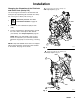
Installation ABOVE-GROUND TRANSFER INSTALLATION KEY J C A B Pump Bleed-type master air valve (required for pump) C Electrically conductive air supply line D Air line quick disconnect E Master air valve (for accessories) F Air line filter G Pump air regulator H Fluid drain valve (required) J Fluid regulator (optional) K Electrically conductive fluid supply hose L Fluid suction line M Underground storage tank N Wall mounting bracket Y Ground wire (required; see page 8 for installation instructions) K A
Installation Grounding WARNING FIRE AND EXPLOSION HAZARD This pump must be grounded. Before operating the pump, ground the system as explained below. Also read the section Fire and Explosion Hazard on page 3. The acetal Husky 515 pump contains stainless steel fibers, which makes the wetted parts conductive. Attaching the ground wire to the grounding screw (106) grounds the wetted parts. See grounding screw on page 25. The metal Husky 716 pumps have a grounding strip connecting the vee clamps (109).
Installation Changing the Orientation of the Fluid Inlet and Outlet Ports (Husky 515) 1 Torque to 80 to 90 in-lb (9 to 10 N m). See Torque Sequence, page 29. You can change the orientation of the fluid inlet and outlet ports by repositioning the manifolds. For Husky 515, see Fig. 4. For Husky 716, see Fig. 5. 1. 109 1 Relieve the pressure. See Pressure Relief Procedure on page 10. outlet 2. Remove the four manifold nuts (109) or bolts (105). 3.
Operation Pressure Relief Procedure WARNING PRESSURIZED EQUIPMENT HAZARD The equipment stays pressurized until pressure is manually relieved. To reduce the risk of serious injury from pressurized fluid, accidental spray, or splashing fluid, follow this procedure whenever you Are instructed to relieve pressure Stop pumping Check, clean, or service any system equipment Install or clean fluid nozzles 1. Shut off the air to the pump. 2. Open the dispensing valve, if used. 3.
Maintenance Lubrication Tightening Threaded Connections The air valve is lubricated at the factory to operate without additional lubrication. If you want to provide additional lubrication, remove the hose from the pump air inlet and add two drops of machine oil to the air inlet every 500 hours of operation or every month. Before each use, check all hoses for wear or damage and replace as necessary. Check to be sure all threaded connections are tight and leak-free. CAUTION Do not over-lubricate the pump.
Troubleshooting Read Pressure Relief Procedure on page 10, and relieve the pressure before you check or service the equipment. Check all possible problems and causes before disassembling the pump. PROBLEM CAUSE SOLUTION Pump will not cycle, or cycles once and stops. Air valve is stuck or dirty. Use filtered air. Pump cycles at stall or fails to hold pressure at stall. Leaky check valves or o-rings. Replace. Worn check balls or duckbill valves or guides. Replace. Check ball wedged in guide.
Service Air Valve (Husky 515 and Husky 716 Pumps) NOTE: Air Valve Repair Kit 241657 is available. Parts included in the kit are marked with a dagger ( ) in Fig. 6 and in the Parts Drawings and Lists. A tube of general purpose grease 111920 is supplied in the kit. Service the air valve as follows. See Fig. 6. NOTES: 1. Relieve the pressure. See Pressure Relief Procedure on page 10.
Service Ball or Duckbill Check Valves NOTE: Fluid Section Repair Kit D05XXX is available. See page 22 to order the correct kit for your pump. Parts included in the kit are marked with a double dagger ( ) in Fig. 7 and Fig. 8 and in the Parts Drawings and Lists. General purpose grease 111920 and Adhesive 113500 are supplied in the kit. 1. Relieve the pressure. See Pressure Relief Procedure on page 10.
Service Husky 515 1 Husky 716 1 109 103 105 107 139 202 301 201 102 139 202 139 202 202 201 301 139 201 201 139 139 106 139 101 202 106 301 202 201 139 102 201 139 139 202 202 201 301 139 201 139 109 1 102 1 Fig. 7 Torque to 80 to 90 in-lb (9 to 10 N-m). See Torque Sequence, page 29. 9067A 1 105 1 Fig. 8 Torque to 80 to 90 in-lb (9 to 10 N-m). See Torque Sequence, page 29.
Service Diaphragms (Husky 515) NOTE: Fluid Section Repair Kit D05XXX is available. See page 22 to order the correct kit for your pump. Parts included in the kit are marked with a double dagger ( ) in Fig. 9 and in the Parts Drawings and Lists. General purpose grease 111920 and Adhesive 113500 are supplied in the kit. Service the diaphragms as follows. See Fig. 9. Disassembly 1. Relieve the pressure. See Pressure Relief Procedure on page 10. 2. Remove manifolds (102 and 103) and fluid covers (101).
6. Put grease on the diaphragm shaft (15), and carefully (do not damage the shaft u-cups) run the diaphragm shaft (15) through the center housing (11) bore. 8. Install the muffler (3). 7. Repeat step 5 for the other end of the diaphragm shaft (15), and torque the fluid-side diaphragm plates (105) to 80 to 90 in-lb (9 to 10 N-m) at 100 rpm maximum. 10. Reinstall the fluid covers (101) and manifolds (102 and 103), and torque the fluid cover and manifold nuts (109) to 80 to 90 in-lb (9 to 10 N-m).
Service Diaphragms (Husky 515) 11 1 4 12 13 114 3 103 7 109 2 15 106 3 416 1 6 402 105 6 401 5 5 4 6 401 4 4 101 6 109 7 102 HD Overmolded Diaphragm Included in Fluid Section Repair Kit D05XXX 109 Fig. 9 18 308981 1 Install with lips facing out of center housing (11). 2 Torque to 35 to 45 in-lb (4.0 to 5.1 N-m). 3 Apply grease. 4 The words “AIR SIDE” on diaphragms (and on backup diaphragms required on PTFE models) must face toward diaphragm shaft (15).
Service Diaphragms (Husky 716) NOTE: Fluid Section Repair Kit D05XXX is available. See page 22 to order the correct kit for your pump. Parts included in the kit are marked with a double dagger ( ) in Fig. 10 and in the Parts Drawings and Lists. General purpose grease 111920 and Adhesive 113500 are supplied in the kit. Service the diaphragms as follows. See Fig. 10. Disassembly 1. Relieve the pressure. See Pressure Relief Procedure on page 10. 2. Remove the manifolds (102) and fluid covers (101).
6. Put grease on the diaphragm shaft (15), and carefully (do not damage the shaft u-cups) run the diaphragm shaft (15) through the center housing (11) bore. 7. Repeat step 5 for the other end of the diaphragm shaft (15), and torque the diaphragm shaft screws (140) to 80 to 90 in-lb (9 to 10 N-m) at 100 rpm maximum. Overmolded Diaphragms: Repeat Step 5 for the other end of the diaphragm shaft (15). 9. Apply thin, even film of grease to inside of vee clamp (109). 10.
Service Diaphragms (Husky 716) 11 416 105 1 7 4 13 102 2 141 3 12 136 3 101 109 4 4 402 5 6 401 15 115 102 6 3 416 1 133 140 5 4 105 6 401 7 Included in Fluid Section Repair Kit D05XXX 1 Install with lips facing out of center housing (11). 2 Torque to 35 to 45 in-lb (4.0 to 5.1 N-m). 3 Apply grease. 4 The words “AIR SIDE” on diaphragms (and on backup diaphragms used on PTFE models) must face toward diaphragm shaft (15).
Husky 515 and Husky 716 Pump Matrix Your Model No. is marked on the pump’s serial plate. To determine a pump Model No. from the following matrix, select the six digits that describe the pump, working from left to right. The first digit is always D, designating Husky diaphragm pumps. The remaining five digits define the air motor type and the materials of construction. For example, a pump with a standard air motor, acetal fluid section, acetal seats, PTFE balls, and PTFE diaphragms is Model D 5 1 2 1 1.
Additional Husky 515 and Husky 716 Pumps Model 241564, 515 pump Same as the D51211 pump, but with an open downward port. Model 241565, 515 pump Same as the D52911 pump, but with an open downward port. Model 248171, 515 pump Same as the D51277 pump, except with split inlets/outlets. Model 248172, 515 pump Same as the D51255 pump, except with split inlets/outlets. Model 248173, 515 pump Same as the D52977 pump, except with split inlets/outlets.
Husky 515 and Husky 716 Common Parts See the Pump Matrix on page 22 for an explanation of the Matrix Column and the Digit. Air Motor Parts List (Matrix Column 2) D Digit Ref. No. Part No.
Husky 515 Parts Drawing Included in Air Valve Repair Kit 241657 109 111 Included in Fluid Section Repair Kit D05XXX 106 grounding screw (acetal pump only) 103 * These parts are unique to the remote operated air motor.
Husky 515 Fluid Section Parts List See the Pump Matrix on page 22 for an explanation of the Matrix Column and the Digit. See page 24 for Air Motor Parts List (Matrix Column 2) Husky 515 Fluid Section Parts List (Matrix Column 3) Acetal Pumps Digit: 1 (NPT) Digit: A (BSPT) Polypropylene Pumps Digit: 2 (NPT) Digit: B (BSPT) PVDF Pumps Digit: 5 (NPT) Digit: E (BSPT) Ref. Ref No. Part No.
Husky 716 Parts Drawing Included in Air Valve Repair Kit 241657 10 Included in Fluid Section Repair Kit D05XXX 8 * These parts are unique to the remote operated air motor.
Husky 716 Fluid Section Parts List See the Pump Matrix on page 22 for an explanation of the Matrix Column and the Digit. See page 24 for Air Motor Parts List (Matrix Column 2) Husky 716 Fluid Section Parts List (Matrix Column 3) Aluminum Pumps Digit: 3 (NPT) Digit: C (BSPT) Ref Ref. No. Part No. Description 101 185622 102* Stainless Steel (sst) Pumps Digit: 4 (NPT) Digit: D (BSPT) Qty Part No.
Torque Sequence Always follow torque sequence when instructed to torque fasteners. Husky 515 Husky 716 1. Left/Right Fluid Covers Torque bolts to 80–90 in–lb (9–10 N m) 1. Left/Right Fluid Covers Torque bolts to 80–90 in–lb (9–10 N m) 3 1 8 5 6 7 4 1 2 2 FRONT VIEW SIDE VIEW 2. Inlet Manifold Torque bolts to 80–90 in–lb (9–10 N m) 2. Inlet Manifold Torque bolts to 80–90 in–lb (9–10 N m) 5 11 10 9 12 3 4 BOTTOM VIEW 6 BOTTOM VIEW 3.
Husky 515 Technical Data Maximum fluid working pressure . . . . . . . . . . . . . . . . . . . . . . . . . . . . . . . . . . . . . . . . . . . 100 psi (0.7 MPa, 7 bar) Air pressure operating range . . . . . . . . . . . . . . . . . . . . . . . . . . . . . . 30 to 100 psi (0.2 to 0.7 MPa, 2.1 to 7 bar ) Operating Temperature Range* Minimum (all pumps) . . . . . . . . . . . . . . . . . . . . . . . . . . . . . . . . . . . . . . . . . . . . . . . . . . . . . . . . . . . . . . 40 F (4 C) Maximum Acetal: . . . . .
Husky 515 Dimensions FRONT VIEW 4.70 in. (119 mm) 1/2 npt(f) or bspt(f) Fluid Outlet * 5.01 in. (127 mm) 1/4 npt(f) Air Inlet * Pumps with duckbill check valves are shipped with the inlet manifold on top and the outlet manifold on the bottom. To make the inlet manifold on the bottom and the outlet manifold on the top, rotate each of the four duckbill assemblies vertically 180 as shown below. 10.63 in. (270.0 mm) 9.94 in. (252.5 mm) 8.56 in. (217.4 mm) 7.75 in. (196.9 mm) 139 201 1.38 in. (35.
Husky 716 Technical Data Maximum fluid working pressure . . . . . . . . . . . . . . . . . . . . . . . . . . . . . . . . . . . . . . . . . . . 100 psi (0.7 MPa, 7 bar) Air pressure operating range . . . . . . . . . . . . . . . . . . . . . . . . . . . . . . 30 to 100 psi (0.2 to 0.7 MPa, 2.1 to 7 bar ) Operating Temperature Range* Minimum (all pumps) . . . . . . . . . . . . . . . . . . . . . . . . . . . . . . . . . . . . . . . . . . . . . . . . . . . . . . . . . . . . . . 40 F (4 C) Maximum Acetal: . . . . .
Husky 716 Dimensions FRONT VIEW * Pumps with duckbill check valves are shipped with the inlet manifold on top and the outlet manifold on the bottom. To make the inlet manifold on the bottom and the outlet manifold on the top, rotate each of the four duckbill assemblies vertically 180 as shown below. 4.25 in. (108.0 mm) 4.44 in. (112.8 mm) 3/4 npt(f), bspt(f), or bspp(f) Fluid Outlet * 1/4 npt(f) Air Inlet 10.43 in. (264.9 mm) 9.18 in. (233.2 mm) 139 7.37 in. (187.2 mm) 7.80 in. (198.1 mm) 201 1.
Husky 515 and 716 Performance Charts Fluid Outlet Pressure Test Conditions: Pump tested in water with inlet submerged. FLUID OUTLET PRESSURE––psi (MPa, bar) 100 (0.7, 7) A Fluid Pressure Curves A at 100 psi (0.7 MPa, 7 bar) air pressure 80 (0.55, 5.5) B at 70 psi (0.48 MPa, 4.8 bar) air pressure C at 40 psi (0.28 MPa, 2.8 bar) air pressure B 60 (0.41, 4.1) 40 (0.28, 2.8) C 20 (0.14, 1.4) 0 0 2 (7.6) 4 (15.2) 6 (22.7) 8 (30.3) 10 (37.
Husky 515 and 716 Performance Charts Air Consumption Test Conditions: Pump tested in water with inlet submerged. ÈÈÈÈÈ ÈÈÈÈÈÈ ÈÈÈÈÈ ÈÈÈÈÈÈ ÈÈÈÈÈÈ ÈÈÈÈÈ ÈÈÈÈÈÈ ÈÈÈÈÈ ÈÈÈÈÈÈ ÈÈÈÈÈÈ ÈÈÈ ÈÈÈÈÈ ÈÈÈÈÈÈ ÈÈÈÈÈÈ ÈÈÈÈÈ ÈÈÈÈÈÈ ÈÈÈÈÈÈ ÈÈÈÈÈ ÈÈÈÈÈÈ ÈÈÈÈÈ ÈÈÈÈÈÈ ÈÈÈÈÈÈ ÈÈÈÈÈ ÈÈÈÈÈ ÈÈÈÈ ÈÈÈÈÈÈ ÈÈÈÈÈÈ ÈÈÈÈÈ ÈÈÈÈ ÈÈÈÈÈÈ ÈÈÈÈÈÈ ÈÈÈÈÈÈ ÈÈÈÈÈ ÈÈÈÈÈÈ ÈÈÈÈÈÈ ÈÈÈÈÈÈ ÈÈÈÈÈÈ ÈÈÈÈÈÈ ÈÈÈÈÈÈ AIR CONSUMPTION––scfm (cubic meters/min) 30 (0.84) A Air Consumption Curves A at 100 psi (0.7 MPa, 7 bar) air pressure 25 (0.
Graco Warranties Graco Standard Husky Pump Warranty Graco warrants all equipment manufactured by Graco and bearing its name to be free from defects in material and workmanship on the date of sale to the original purchaser for use. With the exception of any special, extended, or limited warranty published by Graco, Graco will, for a period of five years from the date of sale, repair or replace any part of the equipment determined by Graco to be defective.