Instructions–Parts List Huskyt750 and Huskyt2000 308703G Surge Suppressors ENG For control of pressure fluctuations and acceleration loss, preventing cavitation. For professional use only. 120 psi (0.8 MPa, 8 bar) Maximum Air Input Pressure 120 psi (0.8 MPa, 8 bar) Maximum Fluid Working Pressure See the Model Numbers on page 12. Important Safety Instructions Read all warnings and instructions in this manual. Save these instructions.
Table of Contents Symbols . . . . . . . . . . . . . . . . . . . . . . . . . . . . . . . . . . . . . . 2 Warnings . . . . . . . . . . . . . . . . . . . . . . . . . . . . . . . . . . . . . . 2 Installation . . . . . . . . . . . . . . . . . . . . . . . . . . . . . . . . . . . . . 4 Operation . . . . . . . . . . . . . . . . . . . . . . . . . . . . . . . . . . . . . 7 Troubleshooting . . . . . . . . . . . . . . . . . . . . . . . . . . . . . . . . 9 Service . . . . . . . . . . . . . . . . . . . . . . . . . . . .
WARNING TOXIC FLUID HAZARD Hazardous fluid or toxic fumes can cause serious injury or death if splashed in the eyes or on the skin, inhaled, or swallowed. D Know the specific hazards of the fluid you are using. D Store hazardous fluid in an approved container. Dispose of hazardous fluid according to all local, state and national guidelines. D Always wear protective eyewear, gloves, clothing and respirator as recommended by the fluid and solvent manufacturer.
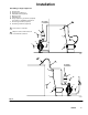
Installation Grounding WARNING FIRE AND EXPLOSION HAZARD When pumping flammable fluids, the surge suppressor must be grounded. Before pumping, ground the system as explained below. Also read the section FIRE OR EXPLOSION HAZARD on page 3. Polypropylene surge suppressors are not conductive. Attaching the ground wire to the grounding lug grounds only the clamp or flange (see Fig. 1).
Installation Grounding a Surge Suppressor A B H S T W Husky pump Husky surge suppressor Fluid drain valve (required) Dispense valve Fluid drain line Surge suppressor ground wire (required) See page 4 for installation instructions. Y Air motor ground wire (required) Z Container ground wire (required) 1 air supply connection 1 Hose must be conductive. H B 2 Dispense valve nozzle must be in contact with the container.
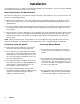
Installation The installations in Fig. 2 are guides for selecting and installing system components. Contact your Graco distributor for assistance in planning a system to suit your needs. Mounting Automatic and Manual Models Be sure the mounting surface can support the weight of the pump, surge suppressor, hoses, and accessories, and the stress caused during operation.
Operation Pressure Relief Procedure WARNING PRESSURIZED EQUIPMENT HAZARD The equipment stays pressurized until pressure is manually relieved. To reduce the risk of serious injury from pressurized fluid, accidental spray from the dispensing device, or splashing fluid, follow this procedure whenever you D D D D Are instructed to relieve pressure Stop pumping Check, clean, or service any system equipment Install or clean fluid nozzles 1. Stop pumping, and shut off the air to the pump. 2.
Operation Charging and Startup For optimum performance, surge suppressors should be charged to a pressure 2 to 10 psi (0.01 to 0.07 MPa, 0.1 to 0.7 bar) lower than system pressure. Manual Models Automatic Models CAUTION Automatic surge suppressors must have the air supply connected before you start pumping. Failure to do so could result in the internal air valve puncturing or rupturing the bladder. CAUTION Manual surge suppressors must be charged before you start pumping.
Troubleshooting Relieve the pressure before checking or servicing the equipment. WARNING To reduce the risk of serious injury whenever you are instructed to relieve pressure, always follow the Pressure Relief Procedure on page 7. Check all possible problems and causes before disassembling the pump. PROBLEM CAUSE SOLUTION Surge suppressor does not hold pressure.
Service Bladder Failure Replacing Bladder or Bellows 1. Relieve the pressure. Normal life for bladders can be from a few months to several years, depending upon the harshness of the application. Below are common reasons for failed bladders or bellows: D Chemical attack: Check chemical compatibility charts. Consult your Graco distributor. D Cut bladder or bellows: Check for sharp objects that may have been introduced into the surge suppressor through pumped fluid.
Service Torque Table Find the proper torque specifications for your surge suppressor unit in the table below. These are the torques to which the clamp band, ring flange, or bolts in bolted units need to be tightened. KEY: plastic = polypropylene or acetal metal = stainless steel rubber = fluoroelastomer or Buna–N Model Bladder Material Housing Material Type of Clamp Torque Husky 2000 rubber plastic clamp band 45 to 55 in-lb (5.1 to 6.
Model Numbers Automatic Husky 750, 3/4-in Surge Suppressors Polypropylene Wetted Bottom Housing and Non-Wetted Top Housing 239096 239121 239122 with Buna–N bladder with PTFE bellows with fluoroelastomer bladder Stainless Steel Wetted Bottom Housing and Non-Wetted Top Housing 239095 239123 239124 with Buna–N bladder with PTFE bellows with fluoroelastomer bladder Automatic Husky 2000, 2-in Surge Suppressors Stainless Steel Wetted Bottom Housing, Polypropylene Non-Wetted Top Housing 239093 239126 239127 w
Parts Matrix Replacement Parts for Huskyt 750 and Huskyt 2000 Surge Suppressors, Series A Parts NOTE: The quantity of every part in this list is 1 for every model. model The X’s indicate the parts that are included in each model. Ref No. Part No.
Parts Drawings (see Parts Matrix on page 13) 8 4 5 24, 25, 26, 28 hanging on regulator C A 8 4 5 9 24, 25, 26, 28 22 hanging on regulator C 21 A 2 3 2 20 22 3 20 B B 06890 Model 239090 14 308703 06889 Model 239091
Parts Drawings (see Parts Matrix on page 13) 2 C 3 8 22 4 10 5 includes fasteners C 24, 25, 27, 28 1 A hanging on regulator A 24, 25, 27, 28 hanging on gauge 11 22 6 7 2 3 14 B 10 B includes fasteners 06893 06886 Model 239088 Model 239126 308703 15
Dimensions Manual Husky 2000 239088 shown Automatic Husky 2000 239126 shown 23.25 in. (591 mm) 22.50 in. (572 mm) 20.25 in. (514 mm) 20.25 in. (514 mm) 8.5 in. (216 mm) 8.5 in. (216 mm) 06894 2 npt fluid inlet 06887 2 npt fluid inlet Manual Husky 750 239091 shown Automatic Husky 750 239096 shown 12.5 in. (318 mm) 13.25 in. (337 mm) 10.0 in. (254 mm) 10.0 in. (254 mm) 6.0 in. (152 mm) 3/4 npt fluid inlet 16 308703 6.0 in.
Technical Data Maximum air input pressure . . . . . . . . . . . . . . . . . . . . . . . . . . . . . . . . . . . . . . . . . . . . . . . . . . . . 120 psi (0.8 MPa, 8 bar) Air line connection . . . . . . . . . . . . . . . . . . . . . . . . . . . . . . . . . . . . . . . . . . . . . . . . . . . . . . . . . . . . . . . . . . . . . . . . . . . . . . 1/4 npt Fluid Inlet size Husky 2000 models . . . . . . . . . . . . . . . . . . . . . . . . . . . . . . . . . . . . . . . . . . . . . . . . . . . . . . . . . . . . .
Graco Standard Warranty Graco warrants all equipment manufactured by Graco and bearing its name to be free from defects in material and workmanship on the date of sale by an authorized Graco distributor to the original purchaser for use. With the exception of any special, extended, or limited warranty published by Graco, Graco will, for a period of twelve months from the date of sale, repair or replace any part of the equipment determined by Graco to be defective.