INSTRUCTIONS-PARTS LIST This manual contains IMPORTANT WARNINGS and INSTRUCTIONS READ AND RETAIN FOR REFERENCE 308–501 Rev A Supersedes 801–642 & 801–643 HYDRA-CLEAN 2245, 3035, 3040 Pressure Washer P/N 800–062, Series B P/N 800–063, Series B 2200 psi (152 bar) OPERATING PRESSURE 2600 psi (179 bar) MAXIMUM WORKING PRESSURE P/N 800–065, Series C P/N 800–335, Series A 3000 psi (207 bar) OPERATING PRESSURE 3400 psi (234 bar) MAXIMUM WORKING PRESSURE GRACO INC. P.O.
WARNING HIGH PRESSURE SPRAY CAN CAUSE SERIOUS INJURY. FOR PROFESSIONAL USE ONLY. OBSERVE ALL WARNINGS. Read and understand all instruction manuals before operating equipment. FLUID INJECTION HAZARD General Safety This pressure washer generates very high fluid pressure. Spray from the gun, leaks or ruptured components can inject fluid through your skin and into your body and cause extremely serious bodily injury including the need for amputation.
EQUIPMENT MISUSE HAZARD General Safety Any misuse of the pressure washer or accessories, such as overpressurizing, modifying parts, using incompatible chemicals and fluids, or using worn or damaged parts, can cause them to rupture and result in fluid injection, splashing in the eyes or on the skin, or other serious bodily injury, fire, explosion or property damage. NEVER alter or modify any part of this equipment; doing so could cause it to malfunction.
MOVING PARTS HAZARD Moving parts can pinch or amputate fingers or other body parts. KEEP CLEAR of moving parts when starting or operating the pressure washer. Pressure Relief Procedure before checking or servicing the pressure washer to prevent discharging high pressure fluid from the gun. NEVER operate the pressure washer without all guards and interlocks installed and functioning. Follow the TERMS WARNING: Alerts user to avoid or correct conditions that could cause bodily injury.
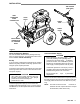
INSTALLATION TEE HANDLE (3040 ONLY) HIGH PRESSURE HOSE CONNECTION HOSE RACK SPRAY GUN SPRAY HOSE INLET WATER CONNECTION 3/4” GARDEN HOSE Figure 1 Check for Shipping Damage The unit should be checked for any damage that may have occurred in shipping. Any damage should be noted and the carrier notified immediately. Set Up If you are using a downstream chemical injector, install it between the pump unloader and the high pressure hose, using the quick couplers provided.
STARTUP Use this procedure whenever starting the pressure washer to help insure that the unit is ready to operate and starting is done safely. 1. Check oil levels. Engine: Add SAE 30 or 10W–30 weight detergent oil as necessary. Pump: Add SAE 20 or 30 weight non–detergent oil as necessary. NOTE: Some units are equipped with a low–oil sensor that shuts the engine of f if the oil level falls below a certain level. If the unit stops unexpectedly, check both the oil and the fuel levels.
Trigger Safety Latch WARNING To reduce the risk of serious bodily injury , including fluid injection, splashing in the eyes or on the skin, ALWAYS engage the trigger safety latch whenever spraying stops, even for a moment. In the engaged position, the trigger safety latch prevents the gun from being triggered accidentally by hand or if it is dropped or bumped. Be sure the latch is pushed fully down when engaging it or it cannot prevent the gun from being triggered. See Figure 2.
SHUTDOWN, FLUSHING AND STORAGE WARNING PRESSURE RELIEF PROCEDURE To reduce the risk of serious bodily injury , including fluid injection and splashing in the eyes, or on the skin, always follow this procedure whenever you stop spraying for more than 10 minutes, when shutting down, and before checking or repairing any part of the system. 1. If the pressure washer will be exposed to freezing temperatures, drain all water out of the pump.
TROUBLESHOOTING CHART WARNING To reduce the risk of serious bodily injury, including fluid injection, splashing in the eyes or on the skin or injury from moving parts, always follow the Pressure Relief Procedure Warning before proceeding. PROBLEM Engine will not start or is hard to start CAUSE SOLUTION No gasoline in fuel tank or carburetor. Fill the tank with gasoline, open fuel shut off valve. Check fuel line and carburetor. Low oil (on units with low oil sensor). Add to proper level.
PARTS DRAWING 800–062 & 800–063 Hydra–Clean 2245 Pressure Washer 51 52 51 1 52 1 8 0 61 69 66 61 69 66 49 74 73 53 42 49 2 48 66 69 45 60 46 41 47 69 79 26 23 28 30 43 25 27 29 31 24 18 71 69 44 3 76 32 71 69 66 66 78 77 62 69 6 66 5 65 11 68 66 69 71 17 67 70 57 36 82 64 37 38 81 75 7 16 13 19 8 10 308-489 72 20 56 15 9 35 66 69 71 69 33 39 63 12 10 50 66 54 55 14 66 4 21 22 81 34 57 58
PARTS LIST 800–062 & 800–063 Hydra–Clean 2245 Pressure Washer REF NO. 1 PART NO.
PARTS DRAWING 800–065 Hydra–Cleanr 3035 Pressure Washer 51 52 1 61 69 66 61 69 66 74 73 53 42 49 2 48 66 69 45 60 46 41 47 69 79 26 23 28 30 43 25 27 29 31 24 18 71 69 44 3 76 32 71 69 66 66 78 77 62 69 6 66 5 65 11 68 66 69 71 17 67 70 39 57 13 37 38 81 75 19 8 12 308-489 72 20 56 15 9 35 64 7 16 40[ 36 82 66 69 71 69 33 63 12 10 50 66 54 55 14 66 4 21 22 81 34 57 58
PARTS LIST 800–065 Hydra–Clean 3035 Pressure Washer REF NO. PART NO.
PARTS DRAWING 800–335 Hydra–Cleanr 3040 Pressure Washer 1 51 52 49 59 74 61 69 66 73 53 42 2 48 66 69 45 60 46 41 47 69 79 26 23 28 30 43 25 27 29 31 24 18 71 69 44 3 76 32 71 69 66 66 78 77 62 69 6 66 5 65 11 68 66 69 71 17 67 70 39 57 13 37 38 81 75 19 8 14 308-489 72 20 56 15 9 35 64 7 16 40[ 36 82 66 69 71 69 33 63 12 10 50 66 54 55 14 66 4 21 22 81 34 57 58
PARTS LIST 800–335 Hydra–Clean 3040 Pressure Washer REF NO. 1 2 3 4 5 6 7 8 9 10 11 12 13 14 15 16 17 18 19 20 21 22 23 24 25 26 27 28 29 30 31 32 33 34 35 36 37 38 39 40 41 42 43 PART NO. DESCRIPTION REF NO.
PARTS DRAWING 800–326 Pump Assembly, 2200 psi 800–327 Pump Assembly, 3000 psi 10 9 8 7 11 2 67 6 5 4 3 1 44 45 46 47 54 10 52 11 9 64 65 63 66 55 60 61 62 53 59 58 57 50 48 51 49 13 19 14 56 20 18 12 12 45 44 43 42 16 17 40 41 14 39 21 28 23 22 38 15 37 31 36 35 26 33 29 32 24 34 25 31 27 30
PARTS LIST 800–326 Pump Assembly, 2200 psi 800–327 Pump Assembly, 3000 psi REF PART NO. NO.
PUMP SERVICE WARNING To reduce the risk of serious bodily injury , including fluid injection, splashing in the eyes or on the skin, or injury from moving parts, always follow the Pressure Relief Procedure Warning before proceeding. NOTE: NOTE: The following metric wrenches are needed: M10, M13 and M30. Repair kits are available. Refer to the individual repair sections and the pump parts page for more details. For the best results, use all parts in the kits.
Servicing the V–Packings NOTE: 5. Thoroughly clean the packing cavities and examine. There are two types of packing kits: one is just packings, the other includes the packings, rings and retainers. 1. Remove the manifold as outlined in the Pumping Section. 6. Lightly grease the packing cavities and then replace the packings in the following order: head ring, v–packing, intermediate ring, head ring, v–packing and packing retainer with the o–ring installed in the retainer groove. CAUTION 2.
THE GRACO WARRANTY WARRANTY AND DISCLAIMERS Graco warrants all equipment manufactured by it and bearing its name to be free from defects in material and workmanship on the date of sale by an authorized Graco distributor to the original purchaser for use. As purchaser’s sole remedy for breach of this warranty, Graco will, for a period of twenty four months from date of sale, repair or replace any part of the equipment proven defective.