INSTRUCTIONS-PARTS LIST 308–530 Rev A This manual contains IMPORTANT WARNINGS and INSTRUCTIONS READ AND RETAIN FOR REFERENCE HYDRA-CLEAN 1535, 2040, 2540 Pressure Washers HYDRA-CLEAN 1535, 5 HP ENGINE P/N 800–698, Series A 1500 psi (103 bar) OPERATING PRESSURE 1900 psi (131 bar) MAXIMUM WORKING PRESSURE HYDRA-CLEAN 2040, 8 HP ENGINE P/N 800–699, Series A 2000 psi (138 bar) OPERATING PRESSURE 2400 psi (165 bar) MAXIMUM WORKING PRESSURE HYDRA-CLEAN 2540, 9 HP ENGINE P/N 800–700, Series A 2500 psi (172 b
INDEX Warnings . . . . . . . . . . . . . . . . . . . . . . . . . . . . . . . . . . . . . . . . . . . . . . . . . . . . . . . 3 Installation . . . . . . . . . . . . . . . . . . . . . . . . . . . . . . . . . . . . . . . . . . . . . . . . . . . . . 5 Startup . . . . . . . . . . . . . . . . . . . . . . . . . . . . . . . . . . . . . . . . . . . . . . . . . . . . . . . . . 6 Shutdown, Flushing and Storage . . . . . . . . . . . . . . . . . . . . . . . . . . . . . . . . . . 8 Maintenance . . . . . . . . . . . . . .
WARNING HIGH PRESSURE SPRAY CAN CAUSE SERIOUS INJURY. FOR PROFESSIONAL USE ONLY. OBSERVE ALL WARNINGS. Read and understand all instruction manuals before operating equipment. FLUID INJECTION HAZARD General Safety This pressure washer generates very high fluid pressure. Spray from the gun, leaks or ruptured components can inject fluid through your skin and into your body and cause extremely serious bodily injury including the need for amputation.
EQUIPMENT MISUSE HAZARD General Safety Any misuse of the pressure washer or accessories, such as overpressurizing, modifying parts, using incompatible chemicals and fluids, or using worn or damaged parts, can cause them to rupture and result in fluid injection, splashing in the eyes or on the skin, or other serious bodily injury, fire, explosion or property damage. System Pressure This sprayer can develop high operating pressures.
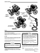
INSTALLATION 1535 2540 HIGH PRESSURE HOSE CONNECTION HIGH PRESSURE HOSE CONNECTION INLET WATER CONNECTION 3/4” GARDEN HOSE INLET WATER CONNECTION 3/4” GARDEN HOSE QUICK COUPLER 2040 SPRAY GUN QUICK COUPLER SPRAY HOSE HIGH PRESSURE HOSE CONNECTION INLET WATER CONNECTION 3/4” GARDEN HOSE Figure 1 Check for Shipping Damage Check the unit for any damage that may have occurred in shipping. Notify the carrier immediately if there is any damage.
STARTUP Always use this startup procedure to ensure that the unit is started safely and properly. 1. Check oil levels. Engine: Add SAE 30 or 10W–30 weight detergent oil as necessary. Pump: Add SAE 20 or 30 weight non–detergent oil or genuine Cat pump oil as necessary. Gear Reducer (2040 and 2540): Add SAE 90 gear oil as necessary . The 1535 uses the oil in pump crankcase. NOTE: All units are equipped with a low–oil sensor that shuts the engine off if the oil level falls below a certain level.
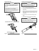
Trigger Safety Latch WARNING To reduce the risk of serious bodily injury , including fluid injection, splashing in the eyes or on the skin, ALWAYS engage the trigger safety latch whenever spraying stops, even for a moment. In the engaged position, the trigger safety latch prevents the gun from being triggered accidentally by hand or if it is dropped or bumped. Be sure the latch is pushed fully down when engaging it or it cannot prevent the gun from being triggered. See Figure 2.
SHUTDOWN, FLUSHING AND STORAGE WARNING Pressure Relief Procedure To reduce the risk of serious bodily injury, including fluid injection and splashing in the eyes, or on the skin, always follow this procedure whenever you stop spraying for more than 10 minutes, when shutting down, and before checking or repairing any part of the system. 1. Engage the trigger safety latch. 2. Turn the sprayer off. 3. Remove the ignition cable from the spark plug. 4. Shut off the water supply. 5.
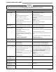
TROUBLESHOOTING CHART WARNING To reduce the risk of serious bodily injury, including fluid injection, splashing in the eyes or on the skin or injury from moving parts, always follow the Pressure Relief Procedure Warning before proceeding. PROBLEM Engine will not start or is hard to start CAUSE No gasoline in fuel tank or carburetor. SOLUTION Dirty air cleaner filter. Spark plug dirty, wrong gap or wrong type. Spray gun closed. Fill the tank with gasoline, open fuel shut off valve.
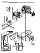
PARTS DRAWING 800–698 Hydra–Clean 1535 Pressure Washer 1 46 6 7 58 53 2 55 54 3 6 45 57 8 4 6 18 17 15 13 14 11 46 12 11 16 23 24 26 20 21 25 19 22 61 63 44 47 28 59 64 46 32 6 56 60 6 48 65 49 66 52 45 39 11 36 27 30 16 27 30 40 31 33 46 41 68 67 36 29 40 67 36 50 51 36 35 10 308–530 6 35 34 42 43
PARTS LIST 800–698 Hydra–Cleanr 1535 Pressure Washer REF PART NO. NO. DESCRIPTION QTY 1 802–239 ENGINE, 5 hp, Briggs & Stratton I/C 1 2 800–695 PUMP & GEAR REDUCER ASSEMBLY (incl. 3, 13) 1 3 804–248 GEAR REDUCER (see page 17) 1 4 802–127 SCREW, Cap, hex hd. 5/16–18 x 1-3/4 4 6 100–527 WASHER, Flat 5/16 20 7 804–250 BRACKET, Support 1 8 801–367 BUMPER, Rubber 2 11 156–849 NIPPLE, Hex 3/8 3 12 802–316 UNLOADER, Preset 1500 psi 1 13 804–244 PUMP ASSEMBLY, 1500 psi (see page 20) 1 14 801–709 PLUG, Square hd.
PARTS DRAWING 800–699 Hydra–Clean 2040 Pressure Washer 57 46 6 7 1 58 2 45 53 6 54 8 3 4 6 15 18 17 14 11 13 12 46 11 16 26 20 23 24 21 25 44 19 22 61 63 47 28 59 64 46 32 56 60 65 66 48 49 6 6 55 52 45 39 11 36 27 30 16 27 30 40 31 46 33 68 41 67 36 29 40 67 36 50 51 36 35 12 308–530 6 35 34 42 43
PARTS LIST 800–699 Hydra–Clean 2040 Pressure Washer REF PART NO. NO. DESCRIPTION QTY 1 802–141 ENGINE, 8 hp, Briggs & Stratton I/C 1 2 800–696 PUMP & GEAR REDUCER ASSEMBLY (incl. 3, 13) 1 3 804–249 GEAR REDUCER (see page 19) 1 4 802–127 SCREW, Cap, hex hd. 5/16–18 x 1-3/4 4 20 6 100–527 WASHER, Flat 5/16 1 7 804–251 BRACKET, Support 2 8 801–367 BUMPER, Rubber 11 156–849 NIPPLE, Hex 3/8 3 1 12 802–315 UNLOADER, Preset 2000 psi 13 804–245 PUMP ASSEMBLY, 2000 psi (see page 22) 1 1 14 801–709 PLUG, Square hd.
PARTS DRAWING 800–700 Hydra–Clean 2540 Pressure Washer 31 11 10 61 3 4 7 43 67 18 10 38 65 60 8 10 51 50 48 47 64 51 49 47 52 13 56 57 37 62 54 58 12 53 17 19 9 2 11 5 34 40 41 55 59 47 66 35 36 42 44 39 15 16 10 10 6 18 24 1 20 15 16 13 11 33 26 63 29 10 11 25 23 32 26 14 20 32 26 28 22 26 27 14 308–530 30 21
PARTS LIST 800–700 Hydra–Clean 2540 Pressure Washer REF PART NO. NO. DESCRIPTION QTY 1 800–392 GUN & WAND ASSEMBLY (incl. 2, 5, 9, 15, 17, 47) 1 2 803–350 GUN, Spray (see Instruction Manual 308–511) 1 1 3 181–867 LABEL, Warning, ventilation 1 4 802–363 LABEL, Caution 1 5 801–134 WAND, 32” 1 6 179–885 LABEL, Warning, chassis 7 803–901 ENGINE, 9 hp, Briggs & Stratton OHV 1 8 802–127 SCREW, Cap, hex hd.
GEAR REDUCER SERVICE (Model 1535) WARNING To reduce the risk of serious bodily injury, including fluid injection, splashing in the eyes or on the skin or injury from moving parts, always follow the Pressure Relief Procedure Warning on page 2 before proceeding. Replacing the O–Ring (5) Replacing the Oil Seal (10) 1. Remove the four bolts, lockwashers and washers. Pull the pump and gear reducer assembly of f the engine. NOTE: 2.
PARTS DRAWING Gear Reducer (Model 1535) 22 23 1 8 20 7 21 6 5 4 3 21 20 24 23 22 16 2 12 10 13 14 17 9 23 19 15 11 PARTS LIST Gear Reducer (Model 1535) REF PART NO. NO. DESCRIPTION 1 804–236 SCREW, Cap, hex hd.
GEAR REDUCER SERVICE (Models 2040 & 2540) WARNING To reduce the risk of serious bodily injury, including fluid injection, splashing in the eyes or on the skin or injury from moving parts, always follow the Pressure Relief Procedure Warning on page 2 before proceeding. Replacing the Gasket (9) Replacing the Oil Seal (14) NOTE: NOTE: To maintain a good seal, the gasket must be replaced whenever the gear reducer is disassembled. 1. Remove the four bolts, lockwashers and washers.
PARTS DRAWING Gear Reducer (Models 2040 & 2540) 27 28 29 12 11 10 22 23 24 30 9 21 32 2 1 26 3 4 7 5 8 6 19 18 17 25 24 15 31 14 16 13 20 PARTS LIST Gear Reducer (Models 2040 & 2540) REF NO. 1 2 3 4 5 6 7 8 9 10 11 12 13 PART NO.
PARTS DRAWING 804–244 Pump Assembly, 1500 psi 18 3 38 20 13 1 9 6 5 17 38 3 12 7 4 8 16 14 11 10 2 20 21 19 25 24 23 38 26 14 22 27 15 16 17 33 34 35 39 40 47 42 43 44 45 46 48 36 48 37 41 39 52 42 20 308–530 43 44 45 46 50 49 51 32 31 30 29 28 3 18
PARTS LIST 804–244 Pump Assembly, 1500 psi REF NO. 1 2 3 4 5 6 7 8 9 10 11 12 PART NO.
PARTS DRAWING 804–245 Pump Assembly, 2000 psi 19 18 16 22 15 20 13 12 7 4 13 14 8 9 3 12 10 11 6 22 2 12 23 28 35 27 26 25 16 17 18 24 21 5 49 48 47 29 46 45 44 43 32 46 44 43 42 41 40 39 42 37 38 45 40 50 51 1 41 308–530 39 34 33 32 30 31 13 20
PARTS LIST 800–245 Pump Assembly, 2000 psi REF NO. 1 2 3 4 5 6 7 8 9 10 11 12 13 14 PART NO.
PARTS DRAWING 804–246 Pump Assembly, 2500 psi 17 15 13 19 12 11 49 50 6 4 49 11 8 7 3 50 1 9 10 5 19 2 20 24 31 23 50 22 13 18 14 21 25 15 16 46 45 44 43 42 35 41 40 32 46 45 44 43 42 41 40 39 38 37 37 39 33 51 52 47 48 24 308–530 36 34 30 29 27 28 26 49 11
PARTS LIST 804–246 Pump Assembly, 2500 psi REF NO. 1 2 3 4 5 6 7 8 9 10 11 PART NO.
PUMP SERVICE (Model 1535) Servicing the Valves Disassembly: 1. Remove the four (4) socket head bolts and spring washers from end of manifold. 2. Support the discharge manifold from the underside and tap with a soft mallet to separate from the inlet manifold. 3. Carefully place discharge manifold on working surface with valve chambers up. 4. From the three (3) smaller diameter and shallow inlet chambers remove the inlet valve adapters with inner and outer o–rings.
4. With crankcase side of manifold down remove hi–pressure seals using a reverse pliers. NOTE: 5. Invert manifold so crankcase side is up and with reverse pliers remove low pressure seals. 3. Examine o–ring and back–up ring on plunger retainer and replace if worn or cut. Lubricate o–ring for ease of installation and to avoid damage to o–rings. Reassembly: 1. Examine low pressure seal for seal wear or spring failure and replace if necessary.
PUMP SERVICE (Models 2040 & 2540) Servicing the Valves Reassembly: 1. Remove the hex valve plug. 1. Carefully examine each ceramic plunger for scoring or cracks, replace if worn and slip onto plunger rod. 2. Examine the o–ring under the plug for cuts or distortion and replace if worn. Lubricate new o–ring before installing. Note: 3. Grasp valve retainer by tab at the top with pliers and remove from valve chamber . Valve parts usually separate during removal.
Reassembly: V–Packing Models: 1. Lubricate high pressure packing area in manifold. 2. Insert male adapter with notches down and “v” side up. 3. Lubricate v–packings and install one–at–a–time with grooved side down. Servicing Crankcase Section 1. While manifold, plungers and seal retainers are removed, examine crankcase seals for wear. 2. Check oil level and for evidence of water in oil. 4. Next install female adapter with grooved side down. 5. Examine seal case o–ring and replace if worn.
ACCESSORIES (Must be purchased separately) DOWNSTREAM CHEMICAL INJECTOR KIT 800–117 & 800–649 ANTI–FREEZE FLUSH KIT 802–327 UPSTREAM CHEMICAL INJECTOR KIT 800–257 INLET PRESSURE REGULATOR 800–258 For injecting harsh cleaning chemicals downstream from the pump. 800–649 is stainless steel construction. For injecting mild cleaning chemicals upstream into the pump. BACKFLOW PREVENTOR 801–133 Prevent back–up of contaminated water into fresh supply. Install upstream of pump.
TECHNICAL DATA Model 800–698 Model 800–699 Model 800–700 Engine (air–cooled, 4 cycle) 5 hp Briggs & Stratton I/C 8 hp Briggs & Stratton I/C 9 hp Briggs & Stratton OHV Gasoline Tank Capacity 3 quarts (2.8 liter) 6 quarts (5.7 liter) 5 quarts (4.8 liter) Water Pump Maximum Working Pressure 1500 psi (103 bar) 2000 psi (138 bar) 2500 psi (172 bar) Water Pump Maximum Flow 3.
THE GRACO WARRANTY WARRANTY AND DISCLAIMERS Graco warrants all equipment manufactured by it and bearing its name to be free from defects in material and workmanship on the date of sale by an authorized Graco distributor to the original purchaser for use. As purchaser’s sole remedy for breach of this warranty, Graco will, for a period of twenty four months from date of sale, repair or replace any part of the equipment proven defective.