INSTRUCTIONS-PARTS LIST This manual contains important warnings and information. READ AND KEEP FOR REFERENCE. 308–367 Rev. B Supersedes Rev. A First choice when and PCN B quality counts. INSTRUCTIONS 23:1 RATIO Monark Sprayers 2760 psi (19.0 MPa, 190 bar) Maximum Fluid Working Pressure 120 psi (0.84 MPa, 8.4 bar) Maximum Air Inlet Pressure Part No. 236–721 Cart Mounted pump Part No. 236–722 Pail Mounted Pump Part No. 236–723 Wall Mount Pump GRACO INC. P.O.
Table of Contents Warnings . . . . . . . . . . . . . . . . . . . . . . . . . . . . . . . . . . . . . . 2 Assembling the Sprayer . . . . . . . . . . . . . . . . . . . . . . . . . 4 Installation . . . . . . . . . . . . . . . . . . . . . . . . . . . . . . . . . . . . 5 Operation . . . . . . . . . . . . . . . . . . . . . . . . . . . . . . . . . . . . . 7 Parts . . . . . . . . . . . . . . . . . . . . . . . . . . . . . . . . . . . . . . . . 10 Technical Data . . . . . . . . . . . . . . . . . . . . . . . . . . . .
WARNING EQUIPMENT MISUSE HAZARD INSTRUCTIONS Equipment misuse can cause the equipment to rupture, malfunction, or start unexpectedly and result in a serious injury. This equipment is for professional use only. Read all the instruction manuals, tags, and labels before operating the equipment. Use the equipment only for its intended purpose. If you are uncertain about usage, call your Graco distributor. Do not alter or modify this equipment. Use only genuine Graco parts and accessories.
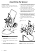
Assembling the Sprayer Cart Mounted Pump Assemble the suction hose (6) to the elbow (5) at the pump intake. Screw the suction tube (7) onto the other end of the hose. See Fig. 1. 4. Screw the elbow (22) into the pump air inlet, so the female threads face down. Apply sealant to both ends of the hose (23). Connect one end to the elbow (22), then connect the other end to the swivel (24) at the pump air regulator (F). 5. Unscrew the filter bowl (T) from the top cap (U).
Installation Be sure that all operators read and understand this entire manual and the separate manuals supplied with components and accessories before using this equipment. Reference numbers and letters in parentheses refer to the figures and parts drawings. Accessories mentioned are available from your Graco distributor. If you supply your own accessories, be sure they area adequately sized to meet your system’s requirements.
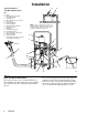
Installation D Typical Installation – Cart Mount Model Shown E KEY A B Pump Bleed-Type Master Air Valve (required for pump) C Air Supply Line D Master Air Valve (for accessories) E Air Line Filter F Pump Air Regulator G Gun Air Regulator H Fluid Drain Valve (required) J Fluid Suction Line K Fluid Filter L Gun Fluid Supply Hose M Gun Air Supply Hose N Air-Assisted Airless Spray Gun P Air Line Lubricator R Fluid Intake Elbow Y Ground Wire (required; see page 5 for installation instructions) NOTE: Some co
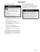
Operation Pressure Relief Procedure WARNING INJECTION HAZARD Fluid under high pressure can be injected through the skin and cause serious injury. To reduce the risk of an injury from injection, splashing fluid, or moving parts, follow the Pressure Relief Procedure whenever you: are instructed to relieve the pressure, stop spraying, check or service any of the system equipment, or install or clean the spray tips. 1. Engage the spray gun safety latch. 2.
Operation Starting and Adjusting the Pump WARNING To reduce the risk of serious injury whenever you are instructed to relieve pressure, always follow the Pressure Relief Procedure on page 7. See Fig. 5. Be sure the air regulators (F, G) and bleedtype master air valve (B) are closed. Do not install the spray tip yet. On cart mount units, place the suction tube (7) in the fluid container. On wall mount units, screw the bung adapter (18) into the container’s bung hole.
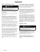
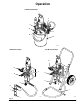
Operation Pail Mounted Pumps F H 36 G 40 46 03145A Wall Mount Pumps Cart Mounted Pumps G G F B B H H F 18 J 7 26 Fig.
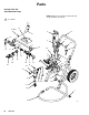
Parts Part No. 236–721 Cart Mounted Pump NOTE: Apply thread sealant to all male threads, except at swivel connections. See Detail.
Parts Ref No. Part No. Description 15 204–560 16 101–180 2 17 102–254 2 2 18 166–999 19 20 162–453 206–994 23 155–665 24 25 26 28 100–840 188–595 165–472 222–297 29 30 158–491 107–142 31 32 150–286 210–658 2 37 224–044 1 47 160–790 HOSE, air; buna-N; 3/8” (10 mm) ID; cpld 3/8 npt(mbe); 18” (457 mm) long 1 GAUGE, air pressure; 0–200 psi (0–1.
Parts Part No. 236–722 Pail Mounted Pump 28 NOTE: Apply thread sealant to all male threads, except at swivel connections.
Parts Part No. 236–722 Pail Mounted Pump Ref No. Part No. Description 3 171–987 4 5 156–823 202–812 6 101–180 7 104–267 9 10 12 13 160–516 165–096 104–765 166–999 14 223–596 15 104–429 16 17 156–971 206–966 18 19 20 162–453 164–259 164–720 22 155–665 TEE; 3/8 npt(f) x 1/4 npt(f) run; 3/8 npt(f) branch UNION, swivel; 1/4 npt(m) x 1/4 npt(f) HOSE, air; neoprene; 1/4” (6 mm) ID; cpld 1/4 npt(mbe); 1.2 ft (0.36 m) long GAUGE, air pressure; 0–200 psi (0–1.
Parts Part No. 236–723 Wall Mount Pump NOTE: Apply thread sealant to all male threads, except at swivel connections. See Detail. Included with wall bracket (7).
Parts Part No. 236–723 Wall Mounted Pump Ref No. Part No. Description 1 3 159–101 214–961 4 5 161–377 223–596 7 207–365 8 206–994 9 10 11 159–100 156–593 156–592 12 156–591 13 156–589 14 15 156–850 218–029 HOUSING, suction tube intake 1 HOSE, suction, fluid; nylon 3/4 npt(mbe); 3/4” (19 mm) ID; 6 ft (1.83 m) long 1 SCREEN, suction tube intake 1 MONARK PUMP See manual 307–619 for parts 1 BRACKET, wall See manual 306–783 for parts 1 THROAT SEAL LIQUID 9 oz (0.
The Graco Warranty Graco warrants all equipment listed in this manual which is manufactured by Graco and bearing its name to be free from defects in material and workmanship on the date of sale by an authorized Graco distributor to the original purchaser for use. With the exception of any special extended or limited warranty published by Graco, Graco will, for a period of twelve months from the date of sale, repair or replace any part of the equipment determined by Graco to be defective.