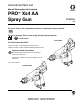
Instructions/Parts List Manual Electrostatic Air-Assisted PRO™ Xs4 AA Spray Gun 309295L ENG For use in Class I, Div. I hazardous locations using Group D spray materials. # 53 For use in Group II, Zone 1 areas using Group IIA spray materials. II 2 G EEx 0.24MJ Smart Model For Professional Use ONLY. 100 psi (0.7 MPa, 7 bar) Maximum Air Inlet Pressure 3000 psi (21 MPa, 210 bar) Maximum Working Fluid Pressure Important Safety Instructions Read all warnings and instructions in this manual.
Table of Contents List of Models . . . . . . . . . . . . . . . . . . . . . . . . . . . . . 3 Warnings . . . . . . . . . . . . . . . . . . . . . . . . . . . . . . . . . 4 Warning Symbol . . . . . . . . . . . . . . . . . . . . . . . . . 4 Caution Symbol . . . . . . . . . . . . . . . . . . . . . . . . . . 4 Warning . . . . . . . . . . . . . . . . . . . . . . . . . . . . . . . . . . 4 Introduction . . . . . . . . . . . . . . . . . . . . . . . . . . . . . . . 6 How the Electrostatic AA Spray Gun Works . . . .
List of Models List of Models Model 244572, Series C PRO Xs4 AA Manual Air-Assisted Spray Gun 309296/3W9296/ 3Z9296 244573, Series C PRO Xs4 AA Manual Air-Assisted Spray Gun with smart display 309296/3W9296/ 3Z9296 309295L Description Operation Manual Part No.
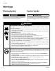
Warnings Warnings Warning Symbol Caution Symbol WARNING CAUTION This symbol alerts you to the possibility of serious injury or death if you do not follow the instructions. This symbol alerts you to the possibility of damage to or destruction of equipment if you do not follow the instructions. WARNING Fire, Explosion, and Electric Shock Hazard Flammable fumes, such as solvent and paint fumes, in work area can ignite or explode.
Warning WARNING Toxic Fluid Hazard Hazardous fluids or toxic fumes can cause a serious injury or death if splashed in the eyes or on the skin, swallowed, or inhaled. • • • Know the specific hazards of the fluid you are using. Read the fluid manufacturer’s warnings. Store hazardous fluid in an approved container. Dispose of the hazardous fluid according to all local, state, and national guidelines. Wear appropriate protective clothing, gloves, eyewear, and respirator.
Introduction Introduction How the Electrostatic AA Spray Gun Works WARNING Skin Injection Hazard Remember, this is not an air spray gun. For your safety, read and follow all Warnings in this manual. The air-assisted spray gun combines airless and air spraying concepts. The spray tip shapes the fluid into a fan pattern, as does a conventional airless spray tip. Air from the air cap further atomizes the fluid and completes the atomization of the fluid tails to produce a uniform pattern.
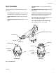
Introduction Gun Overview • ES ON/OFF valve. Turns electrostatics ON (I) or OFF (0). The electrostatic gun includes the following controls. See FIG. 1. • ES INDICATOR (standard gun only). Green when ES is ON (I). • Air cap/tip guard and spray tip. Never spray without the tip guard. See page 46 for spray tip sizes. • Voltage/current DISPLAY (smart models only). Shows voltage (V) and current (A). Green=spray, yellow/red=see Troubleshooting, page 23. • Trigger safety lock.
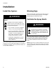
Installation Installation Install the System WARNING Fire, Explosion, and Electric Shock Hazard Installing and servicing this equipment requires access to parts which may cause electric shock or other serious injury if work is not performed properly. • Do not install or service this equipment unless you are trained and qualified. • Be sure your installation complies with National, State and Local codes for the installation of electrical apparatus in a Class I, Div.
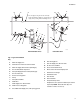
Installation D C* A B* C D The air supply to the gun must be electrically interlocked with the ventilators to prevent the power supply from operating without ventilating fans on. O S Q* P H J* V L M W T *R G *E N F X K U* ti1514b Non-Hazardous Area Hazardous Area Fig. 2.
Installation Connect the Air Line 3. Install a bleed-type air regulator (G, O) on the pump and gun air supply lines to control air pressure to the pump and gun. WARNING Electric Shock Hazard To reduce the risk of electric shock or other serious injury, the air supply hose must be electrically connected to a true earth ground. Use only Graco Grounded Air Supply Hose. 1. Connect the Graco Grounded Air Supply Hose (R) between the air supply line and the gun's air inlet (V).
Installation Connect the Fluid Line Filter the Fluid 1. Before connecting the fluid line (N), blow it out with air and flush it with solvent. Use solvent which is compatible with the fluid to be sprayed. Install a fluid filter (K) at the pump outlet to remove particles and sediment which could clog the spray tip. 2. Install a fluid regulator (M) on the fluid line to control fluid pressure to the gun. The gun includes an inline fluid filter (1) for additional filtration.
Installation Grounding • All persons entering the spray area: shoes must have conductive soles, such as leather, or personal grounding straps must be worn. Do not wear shoes with non-conductive soles such as rubber or plastic. If gloves are necessary, wear the conductive gloves that are supplied with the gun. If non-Graco gloves are worn, cut off fingers or palm area of glove, to ensure your hand contacts the grounded gun handle.
Installation Check Electrical Grounding 3. Turn off the air and fluid supply to the gun. The fluid hose must not have any fluid in it. 4. Make sure the grounded air hose (R) is connected and the hose ground wire is connected to a true earth ground. WARNING Fire, Explosion, and Electric Shock Hazard ti1259a Megohmmeter Part No. 241079 (AA-see FIG. 3.) is not approved for use in a hazardous area.
Installation Check Fluid Resistivity Check Fluid Viscosity To check fluid viscosity you will need: WARNING Fire, Explosion, and Electric Shock Hazard Check the fluid resistivity in a non-hazardous area only. Resistance Meter 722886 and Probe 722860 are not approved for use in a hazardous area. Failure to follow this warning could cause fire, explosion, electric shock and result in serious injury and property damage. Graco Part No.
Operation Operation Refer to the gun operation manual (supplied) for Setup, Shutdown, and Daily Care procedures. INSTRUCTIONS Low Voltage Adjustment (Smart Guns Only) Table 1: Low Voltage Adjustment The ES HI/LO switch enables you to switch between full voltage and a lower voltage output. The lower voltage is factory set, but can be adjusted. 1 2 kV ON ON 70 ON OFF 60 OFF ON 50 OFF OFF 40 1. Set the ES HI/LO switch to LO. 2. Remove the LOW VOLTAGE adjustment plug (53).
Maintenance Maintenance Refer to the gun operation manual (supplied) for Daily Care and Cleaning procedures. INSTRUCTIONS Flush the Spray Gun 1. Turn the ES ON/OFF valve OFF. I ES O Flush the gun before changing colors, at the end of the day, before storing, and before repairing the gun. ti1337a WARNING Fire, Explosion, and Electric Shock Hazard To reduce the risk of fire, explosion, or electric shock, turn the ES ON/OFF valve OFF before flushing the gun.
Maintenance 4. Change the fluid source to solvent, or disconnect the fluid line and connect a solvent supply line to the gun. 6. Relieve the pressure. Lock the trigger. ti1465a 7. Shut off or disconnect the solvent line. 8. Hang the gun from its hook, with the nozzle pointing down. ti1287a 5. Point the gun into a grounded metal pail. Flush until clean solvent flows from the gun. ti1349a ti1465a 309295L 9. When ready to spray again, reconnect the fluid supply line.
Electrical Tests Electrical Tests Electrical components inside the gun affect performance and safety. The following procedures test the condition of the power supply (18) and barrel (16), and electrical continuity between components. CAUTION The barrel resistor cartridge is part of the barrel and is not replaceable. To avoid destroying the gun barrel, do not attempt to remove the barrel resistor. Test Gun Resistance 1. Flush and dry the fluid passage. 2.
Electrical Tests Test Power Supply Resistance 6. Be sure the spring (18b) is in place before reinstalling the power supply. 1. Remove the power supply (18), page 32. 2. Remove the turbine alternator (19) from the power supply, page 33. 3. Measure resistance from the power supply's ground strips (EE) to the spring (18b). See FIG. 6. 4. The resistance should be 135-150 megohms. If outside this range, replace the power supply. If in range, proceed to the next test. 18b 5.
Electrical Tests Test Barrel Resistance 5. If the resistance is still outside the range, replace the barrel. 1. Insert a conductive rod (B) into the gun barrel (removed for the power supply test) and against the metal contact (C) in the front of the barrel. 2. Measure the resistance between the conductive rod (B) and the barrel contact ring (16a). See FIG. 7. The resistance should be 19-29 megohms.
Troubleshooting Troubleshooting WARNING WARNING Electric Shock Hazard Skin Injection Hazard Installing and servicing this equipment requires access to parts which may cause an electric shock or other serious injury if the work is not performed properly. Do not install or service this equipment unless you are trained and qualified. To reduce the risk of a fluid injection injury, always follow the Pressure Relief Procedure on page 24 whenever you are instructed to relieve the pressure.
Troubleshooting Gun Operation Troubleshooting Problem Excessive spray fog. “Orange Peel” finish. Fluid leaks from the fluid packing area Air leaks from the front of the gun Fluid leakage from the front of the gun Gun does not spray Dirty air cap 22 Cause Solution Atomizing air pressure too high. Close atomizing air valve some, or decrease air pressure as low as possible; minimum 40 psi (0.28 MPa, 2.8 bar) needed at gun for full voltage. Fluid too thin. Increase viscosity.
Troubleshooting Electrical Troubleshooting Problem Poor wrap. ES indicator or voltage/current display is not lit. Cause ES ON/OFF valve OFF (0).* Gun air pressure too low. Turn ON (I). Check air pressure to gun; minimum 40 psi (0.28 MPa, 2.8 bar) needed at gun for full voltage. Atomizing air pressure too high. Decrease. Fluid velocity too high. Decrease fluid pressure or replace worn tip. Incorrect distance from gun to part. Should be 8-12 in. (200-300 mm). Poorly grounded parts.
Repair Repair Pressure Relief Procedure 4. Unlock the trigger. WARNING ti1406a 5. Trigger the gun into a grounded metal waste container to relieve the fluid pressure. Skin Injection Hazard The system pressure must be manually relieved to prevent the system from starting or spraying accidentally. Fluid under high pressure can be injected through the skin and cause serious injury.
Repair Prepare the Gun for Service WARNING • Only use genuine Graco parts. Do not mix or use parts from other PRO Gun models. Note that the air cap, spray tip, and tip guard for this gun are orange. • Air Seal Repair Kit 244781 is available. The kit must be purchased separately. Kit parts are marked with an asterisk, for example (6*).
Repair Tip Guard, Air Cap, Spray Tip, or Seat Housing Replacement 1. Prepare gun for service, page 25. CAUTION The barrel resistor cartridge (B) is part of the barrel and is not replaceable. To avoid destroying the gun barrel, do not attempt to remove the barrel resistor. 2. Remove the retaining ring (27), tip guard (4), air cap (9a), and spray tip (3). You may have to turn the air cap with the tip guard to remove it. See FIG. 8. 3. Replace the tip gasket (3a) if damaged.
Repair CAUTION CAUTION To avoid damaging the seat housing and gun barrel, never over-tighten the seat housing. Over-tightening may result in improper fluid shut-off. To avoid damaging the tip guard (4), orientate the air cap (9a) before tightening the retaining ring (27). Do not turn the cap when the retaining ring is tight. 5. Trigger the gun and install the gray-colored seat housing (2). Tighten until snug, then 1/4 turn more. 6. Assemble the spray tip (3), air cap (9a), and tip guard (4).
Repair Electrode Replacement WARNING Electric Shock Hazard To reduce the risk of fire, explosion, or electric shock, do not operate the spray gun without the electrode installed in the air cap. 4. Push the new electrode through the air cap hole. Make sure the short end (BB) of the electrode engages the hole (CC) in the back of the air cap. Press the electrode in place firmly with your fingers. See FIG. 10. 5. Install the air cap assembly, page 26. 6. Test gun resistance, page 18. 9b 1.
Repair Fluid Tube Replacement Fluid Filter Removal 1. Prepare the gun for service, page 25. 1. Prepare the gun for service, page 25. 2. Disconnect the bottom fluid tube nut (C). See FIG. 11. 2. Disconnect the bottom fluid tube nut (C). 3. Remove the fluid filter (1) from the fluid fitting. Clean or replace the filter, as needed. See FIG. 12. 3. Carefully unscrew the top fluid tube nut (D). NOTE: Replacement filters are available in 100 mesh (standard) or 60 mesh sizes. See page 45.
Repair Fluid Needle Replacement 1. Prepare the gun for service, page 25. 55 2. Remove the air cap assembly and seat housing, page 26. 26a 45 8 3. Remove the barrel (16), page 31. 4. Remove the trigger screws (8) and trigger (30). 30 TI1618A 5. Remove the spring cap (45) and the spring (26a) from the barrel. See FIG. 13. Fig. 13. Spring Cap and Springs 6. Place the 2 mm driver (44) in the back of the fluid needle assembly.
Repair Barrel Removal 2. Place the barrel (16) over the power supply (18) and onto the gun handle (17). 1. Prepare the gun for service, page 25. 3. Tighten the three screws (11) oppositely and evenly (about a half turn past snug). 2. Carefully loosen the nut (C) from the bracket fluid fitting (13). See FIG. 16. CAUTION 3. Loosen the three screws (11). Do not over-tighten the screws (11). CAUTION To avoid damaging the power supply (18), pull the gun barrel straight away from the gun handle.
Repair Power Supply Removal and Replacement NOTE: • Inspect the gun handle power supply cavity for dirt or moisture. Clean with a clean, dry rag. • Do not expose gasket (10) to solvents. 1. Prepare gun for service, page 25. 2. Remove the barrel (16), page 31. CAUTION 7. Connect the 3-wire connector (B). Slide the alternator (19) down onto the power supply (18). 8. Lubricate the alternator o-ring (19a*) with non-silicone grease, Part No. 111265. Do not over-lubricate. 9.
Repair Turbine Alternator Removal and Replacement NOTE: Replace turbine bearings after 2000 hours of operation. Order Part No. 223688 Bearing Kit. 1. Prepare gun for service, page 25. 2. Remove the power supply/alternator assembly, page 32. 4. Measure resistance between the two outer terminals of the 3-wire connector (B); it should be 2.5-3.5 ohms. If outside this range, replace the alternator coil. 5. Follow the bearing replacement procedure in the bearing kit manual 308034. 6.
Repair Atomizing Air Adjustment Valve Repair 6. Clean all parts and inspect for wear or damage. 1. Prepare the gun for service, page 25. 7. When reassembling the atomizing air valve (20), lightly lubricate the valve threads and screw the stem (20d) fully into the housing (20c) until bottomed. Install the o-ring (20b*), lubricate, and unscrew the valve stem until the o-ring enters the housing. 2. Place a wrench on the flats of the valve assembly (20) and unscrew it from the handle (17).
Repair Air Valve Repair 5. Inspect the u-cup (6*). Do not remove the u-cup unless damaged. If removed, install the new one with its lips facing into the gun handle (17). 1. Prepare the gun for service, page 25. 2. Remove the barrel, page 31. 6. Install the air valve (21) and spring (15) into the gun handle (17). 3. Remove the air valve cap (25) from the handle (17). Remove the spring (15). See FIG. 20. 7. Install the air valve cap (25). Torque to 15-25 in-lb (1.7-2.8 N•m). 8.
Repair ES ON/OFF Valve Repair 4. Clean and inspect parts for damage. Replace if necessary. 1. Prepare the gun for service, page 25. NOTE: The protrusion on the retainer plate (22d) must point upward. 2. Loosen the screw (48). Remove the valve. 3. Lubricate the o-rings (22a* and 22b*) with non-silicone grease, Part No. 111265. Do not over-lubricate. 5. Reinstall the valve. Torque the screw (48) to 15-25 in-lb (1.7-2.8 N•m). 22d 22g 22e 22b* CAUTION Do not over-lubricate parts.
Parts Parts Part No. 244572 85 kV Electrostatic Gun, Series C (items 1-50) See page 38 for detail views of the alternator (19), atomizing air adjustment valve (20), and ES ON/OFF valve (22).
Parts Ref. No. 19: Alternator Ref. No. 20: Atomizing Air Adjustment Valve 20d 19a* 19b 20b* TI1487A 20c 19b 20a TI1481a 19e 19d 19c Ref. No.
Parts Part No. 244572 85 kV Electrostatic Gun, Series C (items 1-50) Ref. No. Part No. Description 1 205264 FILTER, fluid, inline 1 2 245280 HOUSING, seat 1 3 GG3XXX SPRAY TIP (customer’s choice); includes item 3a 1 Qty Ref. No. Part No. Description 20 244556 VALVE, adjustment, atomizing air; includes items 20a-20d 1 20a 101021 . RING, retaining 1 20b* 106560 . O-RING; fluorocarbon 1 Qty 3a 183459 . SEAL, spray tip 1 20c 197566 .
Parts Ref. No. Part No. Description 41 244915 COVER, gun; box of 10 (not shown) 1 42 179791 TAG, warning (not shown); replacement available at no cost 1 43 180060 SIGN, warning (not shown); replacement available at no cost 1 44 112080 TOOL, needle; 2 mm 1 45 198516 CAP, spring 47 197967 PLUG 40 Qty Ref. No. Part No.
Parts Part No. 244573 85 kV Electrostatic Gun, Series C (items 1-59) See page 42 for detail views of the alternator (19), atomizing air adjustment valve (20), and ES ON/OFF valve (22).
Parts Ref. No. 19: Alternator Ref. No. 20: Atomizing Air Adjustment Valve 20d 19a* 19b 20b* TI1487A 20c 19b 20a TI1481a 19e 19d 19c Ref. No. 22: ES ON/OFF Valve 22e 22d 22f 22g 22b* 22c 22a* 48 TI1488A Part No. 244573 85 kV Electrostatic Gun, Series C (items 1-59) Ref. No. Part No. Description 1 9b 244917 . ELECTRODE (kit of 5) 1 HOUSING, seat 1 10* 197517 GASKET, barrel 1 GG3XXX SPRAY TIP (customer’s choice); includes item 3a 1 11 197518 SCREW; socket-hd; 10-24 x 3/4 in.
Parts Ref. No. Part No. Description Qty Ref. No. Part No. Description 18 244541 POWER SUPPLY, 85 kV; includes items 18a-18b 1 27a* 198307 . PACKING, u-cup 1 18a* 28 276695 HOOK 1 103337 . O-RING; fluoroelastomer 1 30 276698 TRIGGER 1 18b 197624 . SPRING, compression 1 35 185105 FITTING, air; left-hand threads 1 19 244555 TURBINE, alternator; includes items 19a-19e 1 36 107460 WRENCH, ball end; 4 mm 1 19a* 110073 .
Accessories Accessories Air Line Accessories Air Line Quick Disconnect 112534 Swiveling quick disconnect replaces standard air inlet swivel. AirFlex™ Flexible Grounded Air Hose 100 psi (7 bar, 0.7 MPa) Maximum Working Pressure 0.315 in. (8 mm) ID; 1/4 npsm(f) x 1/4 npsm(f) left-hand thread 244963 6 ft (1.8 m) 244964 15 ft (4.6 m) 244965 25 ft (7.6 m) 244966 36 ft (11 m) 244967 50 ft (15 m) 244968 75 ft (23 m) 244969 100 ft (30.5 m) Standard Grounded Air Hose 100 psi (7 bar, 0.
Accessories Gun Accessories Gun Repair Kit 244781 Air Seal Repair Kit Electrode Replacement Kit 244917 Includes five electrodes. Cleaning Brush 105749 Miscellaneous Accessories Ground Wire and Clamp 222011 Inline Fluid Filters 238561 238563 100 mesh filter. Set of three. 60 mesh filter. Set of three. 241079 Replaces inlet fitting with ball valve to shut off air during flushing. Converts ES ON/OFF valve to always ON condition.
Spray Tip Selection Chart Spray Tip Selection Chart 46 Part No. Fan Width at 10 in. (250 mm) in. (mm) Orifice Size in. (mm) GG3107 2-4 (50-100) 0.007 (0.
Technical Data Technical Data Category Data Maximum Working Fluid Pressure 3000 psi (21 MPa, 210 bar) Maximum Working Air Pressure 100 psi (0.7 MPa, 7 bar) Minimum Air Pressure to Gun Inlet 40 psi (0.28 MPa, 2.8 bar) Maximum Fluid Operating Temperature 120°F (48°C) Paint Resistivity Range 3 megohm/cm to infinity Short Circuit Current Output 125 microamperes Voltage Output PRO Xs4 AA (244572): 85 kV PRO Xs4 AA (244573): 40-85 kV Sound Power (measured per ISO Standard 9216) at 40 psi (0.
Graco Standard Warranty Graco warrants all equipment manufactured by Graco and bearing its name to be free from defects in material and workmanship on the date of sale to the original purchaser for use. With the exception of any special, extended, or limited warranty published by Graco, Graco will, for a period of twelve months or two thousand hours of operation from the date of sale, repair or replace any part of the equipment determined by Graco to be defective.