Repair and Parts Visit our website; http://MAGNUM.Graco.com X5™ , X7™ , ProX7™ & ProX9™ Airless Sprayers 312667B - For portable spray applications of architectural paints and coatings - (See specifications, page 2.) US Patent 6,752,067 European Patent 1 208 287 Korean Patent 10-0668583 IMPORTANT SAFETY INSTRUCTIONS. Read all warnings and instructions in this manual. Save these instructions.
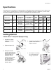
Specifications Specifications This equipment is not intended for use with flammable or combustible materials used in places such as cabinet shops or other “factory”, or fixed locations. If you intend to use this equipment in this type of application, you must comply with NFPA 33 and OSHA requirements for the use of flammable and combustible materials. Maximum Working Pressure Dispense Rate gpm (lpm) Hose Length and Diameter Gun Model PSI MPa bar A 0.24 gpm (0.91 lpm) 1/4 in. x 25 ft (6.4 mm x 7.
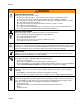
Warnings Warnings The following warnings are for the setup, use, grounding, maintenance, and repair of this equipment. The exclamation point symbol alerts you to a general warning and the hazard symbols refer to procedure-specific risks. Refer back to these warnings. Additional, product specific warnings may be found throughout the body of this manual where applicable. Grounding Instructions This product must be grounded.
Warnings WARNING FIRE AND EXPLOSION HAZARD Flammable fumes, such as solvent and paint fumes, in work area can ignite or explode. To help prevent fire and explosion: • Do not spray flammable or combustible materials near an open flame or sources of ignition such as cigarettes, motors, and electrical equipment. For X5 and X7 models: only use water-based or mineral spirit-type materials with a flash point greater than 70° F (21° C).
Warnings WARNING EQUIPMENT MISUSE HAZARD Misuse can cause death or serious injury. • Always wear appropriate gloves, eye protection, and a respirator or mask when painting. • Do not operate or spray near children. Keep children away from equipment at all times. • Do not overreach or stand on an unstable support. Keep effective footing and balance at all times. • Stay alert and watch what you are doing. • Do not operate the unit when fatigued or under the influence of drugs or alcohol.
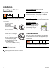
Installation Installation Grounding and Electric Requirements Fluid supply container: follow local code. Sprayer must be grounded. Grounding reduces the risk of static and electric shock by providing an escape wire for electrical current due to static build up or in the event of a short circuit. Grounding the metal pail: connect a ground wire to the pail by clamping one end to pail and other end to ground such as a water pipe.
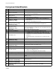
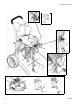
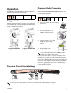
Component Identification Component Identification A Airless spray gun Sprays fluid. B Power switch Turns sprayer ON and OFF. C Pressure control knob Increases (clockwise) and decreases (counter-clockwise) fluid pressure in pump, hose, and spray gun. C1 Setting Indicator To select function, align symbol on pressure control knob with setting indicator, page 9. D Pump fluid outlet fitting Threaded connection for paint hose.
Component Identification ti9724a ti9346a W U B K J F F1 N ti9670a H X C G C1 ti9368a AA L R E S V A Q V T M 8 ti9669a D ti9667a (SG20) (SG10) ti11455a ti9668a 312667B
Operation Operation Pressure Relief Procedure See Operation manual 312001 for basic information on sprayer set-up, flushing, and storage. Follow this Pressure Relief Procedure whenever you stop spraying and before cleaning, checking, servicing, or transporting equipment. Trigger Lock 1. Turn power switch OFF and unplug power cord. Always engage the trigger lock when you stop spraying to prevent the gun from being triggered accidentally by hand or if dropped or bumped. ti2018a 2.
General Repair Information General Repair Information To reduce risk of serious injury, including electric shock: • Do not touch moving or electric pars with fingers or tools while testing repair. Flammable materials spilled on hot, bare, motor could cause fire or explosion. To reduce risk of burns, fire or explosion, do not operate sprayer with cover removed. • Keep all screws, nuts, washers, gaskets, and electrical fittings removed during repair procedures.
Basic Troubleshooting Basic Troubleshooting Check everything in this Basic Troubleshooting table before you bring the sprayer to a Graco/MAGNUM authorized service center. Problem Power switch is on and sprayer is plugged in, but motor does not run, and pump does not cycle. Cause Pressure is set at zero pressure. Solution Turn pressure control knob clockwise to increase pressure setting. Electric outlet is not providing power.
Basic Troubleshooting Problem Pump does not prime. Cause Solution Prime/Spray Valve is in SPRAY posi- Turn Prime/Spray Valve to PRIME tion. position (pointing down). Inlet screen is clogged or suction tube is not immersed. Clean debris off inlet screen and make sure suction tube is immersed in fluid. Pump was not primed with flushing fluid. Remove suction tube from paint. Prime pump with water or solvent-based flushing fluid, see Operation manual 312001. Inlet valve check ball is stuck.
Basic Troubleshooting Problem Pump cycles but does not build up pressure. Pump cycles, but paint only dribbles or spurts when spray gun is triggered. 312667B Cause Solution Prime/Spray valve in PRIME position Turn Prime/Spray valve to SPRAY (pointing down). position (pointing forward). Pump is not primed. Prime pump, see Operation manual 312001. Inlet screen is clogged or suction tube is not immersed. Clean debris off inlet screen and make sure suction tube is immersed in fluid.
Basic Troubleshooting Problem Cause Pressure is set at maximum but Spray tip is clogged. cannot achieve a good spray pattern. Solution Unclog spray tip, see Operation manual 312001. Reversible spray tip is in UNCLOG position. Rotate arrow-shaped handle on spray tip so it points forward on gun. Spray tip is too large for sprayer. Select smaller spray tip. Spray tip is worn beyond capability of Replace spray tip. sprayer. Extension cord is too long or not heavy enough gauge. Replace extension cord.
Basic Troubleshooting Problem Cause Solution Fan pattern varies dramatically while Pressure control switch is worn and Take sprayer to Graco/MAGNUM causing excessive pressure variation. authorized service center. spraying. OR Sprayer does not turn on promptly when resuming spraying. Cannot trigger spray gun. Spray gun trigger lock is locked. Rotate trigger safety lever to unlock trigger lock, page 9. Paint is coming out of pressure control switch. Pressure control switch is worn.
Advanced Troubleshooting Advanced Troubleshooting See Basic Troubleshooting first, page 11 for problems that are more easily remedied. General Problem: Motor Does Not Operate Specific Problem Cause Solution Power switch is on and sprayer See Basic Troubleshooting, is plugged in; pump does not page 11. cycle. Basic mechanical problems. Paint is frozen or hardened in pump. Unplug sprayer from electrical outlet.
Advanced Troubleshooting Specific Problem Basic electrical problems. Cause Solution Motor overheated. Allow motor to cool for 45 minutes. Retry. Electrical outlet is damaged. Reset building circuit breaker or replace fuse. Try another outlet. Check electric supply with volt meter. Meter must read 85 to 130V AC. If voltage is too high, do not plug sprayer in until outlet is corrected. Control board leads are improperly fastened, improperly mated, or corroded. Replace any loose terminals.
Advanced Troubleshooting Specific Problem Sprayer Wiring Problems Cause Sprayer power cord damaged. Solution Unplug sprayer power cord. Disconnect black power cord wire at power switch. NOTE: Remove enclosure mounting screws and pull enclosure away from drive housing. Take care not to pull on leads from electrical cord and power switch. Unplug in-line connection white cord wire. Plug in power cord. Test voltage between black and white wires of power cord. Meter must read 85 to 130V AC.
Advanced Troubleshooting General Problem: Circuit Breaker is Tripping Specific Problem Building circuit breaker opens as soon as sprayer is turned on. NOTE: Remove enclosure mounting screws and pull enclosure away from drive housing. Take care not to pull on leads from electrical cord and power switch. Cause Sprayer electrical wiring is pinched or insulation is damaged. Repair or replace any damaged wiring or terminals. Securely reconnect wires.
Advanced Troubleshooting General Problem: Erratic Motor Operation Specific Problem Sprayer quits after running for 5 to 10 minutes Cause Solution Building circuit is overloaded. Remove other loads from building circuit or find another circuit that has less load. See Grounding and Electric Requirements, page 6. Electrical outlet supplying wrong voltage. Try another outlet. Check electric supply with volt meter. Meter must read 85 to 130V AC. If voltage is too high, do not use outlet until corrected.
Advanced Troubleshooting General Problem: Low or Fluctuating Output Specific Problem Cause Solution Pump cycles, but output is low or See Basic Troubleshooting, surging. page 11. Worn or obstructed inlet and outlet valves. Check for worn pump valves as follows: Prime sprayer with paint. Turn the Prime/Spray valve to SPRAY position. Turn pressure control fully clockwise. Trigger spray gun briefly. When spray gun trigger is released pump should cycle momentarily and stop.
Advanced Troubleshooting Specific Problem Cause Motor runs and pump cycles, Intake valve or outlet valve is but pressure does not build up. not seating properly. Pump packings are worn or damaged. Solution Remove and clean inlet valves and outlet valves. Replace if necessary. See List of Kits, page 26. Check for leaking around pump. ProX7 and ProX9: Replace pump packings. See List of Kits, page 26. X5 and X7: Replace complete pump. See List of Kits, page 26.
Motor Diagnostics (X5 and X7) Motor Diagnostics (X5 and X7) If Motor Diagnostics reveal a damaged motor or if motor brushes are shorter than 1/4 in. (6.4 mm) replace the motor using Motor Kit, page 26. Setup 1. Unplug power cord and Relieve Pressure, page 9. 2. Remove enclosure and disconnect two black motor leads to control board (see Wiring Diagram, page 36). 3. Remove motor fan cover by gently prying up on retention tabs on sides of motor. Motor shaft should spin easily when turning fan.
Pressure Control Switch Diagnostics Pressure Control Switch Diagnostics ProX7, ProX9, X5, and X7 If pressure control switch diagnostics reveal a damaged pressure control, replace it with the correct Pressure Control Switch Kit, see page 26. X5 and X7 sprayers have different pressure control kits because stall pressure is preset at the factory. 1. Unplug power cord and Relieve Pressure, page 9. 2.
Control Board Diagnostics (ProX7 and ProX9) Control Board Diagnostics (ProX7 and ProX9) Check for motor problems before replacing control board. A damaged motor may burn out a good control card. Check for a damaged control board or pressure control switch as follows: 7. Attach harness from a pressure control switch you know is functioning correctly to control board. Pressure control switch does not have to be installed in pump. 1. Relieve Pressure, page 9. 2. Unplug electrical cord. 3.
List of Kits List of Kits Kit Number 26 Models 289107 288706 288705 288900 244035 289680 289681 289695 287770 288747 X5, X7, ProX7, ProX9 X5, X7 ProX7 ProX9 X5, X7, ProX7, ProX9 X5 X7 ProX7, ProX9 ProX7, ProX9 ProX7, ProX9 289682 288692 119276 119277 289209 289102 247339 247340 243082 256212 262011 262012 262013 262014 289915 289104 289989 244266 244267 235014 288701 288700 288699 289878 243094 288818 289650 288703 288702 255107 255108 197607 15T122 15K617 288709 X5, X7 ProX7, ProX9 ProX7 ProX9 X5, X
Parts Parts X5 Model 262800 Parts List Ref Part Description 1 1a 1b▲ 7 7a▲ 7b▲ 14 14a 14b 16 17 22 23 24 25 26 29 289682 120724 15R605 244266 15A464 15K530 289650 289209 115477 289915 289878 235014 224807 187625 111600 196574 288701 29a 29b 30 31 32 32a 33 34 35 36 37 38 39 40 105445 115719 289107 15R549 288706 115492 243082 244035 115489 195084 197607 116295 195400 118899 KIT, housing cover, includes 1a, 1b SCREW LABEL, Magnum X5, front KIT, pressure control, includes 7a, 7b LABEL, control LABEL KI
Parts X5 Model 262800 16 7a 14 14b 66 7b 7 32a 1 32 1a 31 30 14a 22 17 1b 23 25 26 29 29a 24 29b 39 38 39 37 35 36 ti11318a 33 35 34 28 312667B
Parts X5, Model 262800 41 71 72 70 41a 67a 40 86 41 67 68 67b 41b 44 51 85 43 47a ti11319a 85a 47 84 312667B 29
Parts X7 Model 262805 Parts List Ref Part Description 1 1a 1b▲ 7 7a▲ 7b▲ 14 14a 14b 16 17 22 23 24 25 26 29 289682 120724 15R606 244267 15A464 15K530 289650 289209 115477 289915 289878 235014 224807 187625 111600 196574 288701 29a 29b 30 31 32 32a 33 34 35 36 37 38 39 40 41 105445 115719 289107 15R549 288706 115492 243082 244035 115489 195108 15T122 116295 195400 118899 289681 41a▲ 41b 41c 41d 15E072 115477 121481 120093 KIT, housing cover, includes 1a, 1b SCREW LABEL, Magnum X7, front KIT, pressu
Parts X7 Model 262805 16 14b 14 7a 7b 66 7 32a 32 31 14a 30 1a 22 23 25 17 29 1b 29a 1 29b 38 32a 24 26 35 62 39 36 37 35 33 34 ti11320a 312667B 31
Parts X7 Model 262805 41a 86 41 71 70 41b 68 40 57 58 41 41c 67a 47a 43 56 72 52 44 41d 60 67 67b 53 54 51 85 47 85a 55 84 32 ti11321a 312667B
Parts ProX7 and ProX9 Models 261815 and 261820 Parts List Ref Part 1 2 3 4 5 6 15J632 15J633 15J641 15J675 15J678 15J940 15J691 15J695 15J699 247313 119547 247314 15J941 15J949 15J950 15J984 15J985 288458 112612 15J681 115477 117630 120688 120689 15K617 243082 116295 195108 244035 115489 115099 235014 115648 187625 224807 247340 289102 244168 118899 288695 Qty LEG 2 SUPPORT, frame 2 PULL ROD 1 SPACER, frame 4 BRACKET 2 AXLE PIN, ProX7 2 AXLE PIN, ProX9 2 TUBE CAP 2 TUBE CAP 4 ACTUATOR 1 NUT, hex, lock,
Parts ProX7 and ProX9 Models 261815 and 261820 45c 85 45d 116 45b 66 44 47 45 45a 68a 85 42 46 59 52 67 63c 67c 62a 67b 59a 56 62b 68 62 63d 50 58 49 55 63a 37 51 63 63e 67a 39 63b 23 110 34 40 31 32 57 53 29 81 35 34 33 41 30 34 ti9503a 312667B
Parts ProX7 and ProX9 Models 261810 and 261820 9 17 3 27 28 15 16 12 75 20 83 9 18 22 8 81 76 23 5 25 77 82 8 21 6 75 19 2 4 4 1 10 81 ti9504a 7 312667B 35
Wiring Diagrams Wiring Diagrams X5 and X7 Models 262800 and 262805 /. /&& 37)4#( 0/7%2#/2$ ",!#+ 7)2% 0/7%2#/2$ 7()4% 7)2% !54/ 02)-% 0/7%2#/2$ '2%%. 7)2% 7()4% "/!2$ 7)2% ! &53% #(!33)3 '2/5.$ Ref 67a ",!#+ -/4/2 ,%!$ 02%3352% 37)4#( Thermal Switch 1 ",!#+ -/4/2 ,%!$ 7)2).' $)!'2!- ti11322c 1 When assembling motor to pump housing, make sure Thermal Switch is positioned on top as shown above.
Wiring Diagrams ProX7 and ProX9 Models 261815 and 261820 /. /&& 37)4#( !54/ 02)-% , * * ",+ ",+ , 02%3352% 37)4#( '2. #/.42/, "/!2$ #(!33)3 '2/5.$ 0/7%2 #/2$ 2%& 7(4 7(4 ti9505a 7)2).
Technical Data Technical Data MAGNUM X5 MAGNUM X7 MAGNUM ProX7 MAGNUM ProX9 Working pressure range 0-2800 psi 0-3000 psi 0-3000 psi (0-19 MPa, 0-193 bar) (0-21 MPa, 0-207 bar) (0-21 MPa, 0-207 bar) Electric motor 6.0A 6.0A 5.8A (open frame, 9.4A (open frame, (open frame, universal) (open frame, universal) permanent magnet DC) permanent magnet DC) Operating horsepower 0-3000 psi (0-21 MPa, 0-207 bar) 1/2 5/8 3/4 7/8 0.24 gpm (0.91 lpm) 0.31 gpm (1.17 lpm) 0.34 gpm (1.29 lpm) 0.38 gpm (1.
Graco Standard Warranty Graco Standard Warranty Graco warrants all equipment referenced in this document which is manufactured by Graco and bearing its name to be free from defects in material and workmanship on the date of sale to the original purchaser for use. With the exception of any special, extended, or limited warranty published by Graco, Graco will, for a period of twelve months from the date of sale, repair or replace any part of the equipment determined by Graco to be defective.
All written and visual data contained in this document reflects the latest product information available at the time of publication. Graco reserves the right to make changes at any time without notice. MM 312667 Graco Headquarters: Minneapolis International Offices: Belgium, China, Japan, Korea GRACO INC. P.O. BOX 1441 MINNEAPOLIS, MN 55440-1441 www.graco.