Owners Manual 333394P EN Project Series Paint Sprayers Important Safety Instructions Read all warnings and instructions in this manual and on the unit, including the power cord. Be familiar with the controls and the proper usage of the equipment. Save these instructions. Scan QR code or click on link for operational video. http://graco.com/tc360opvid ti23409b WARNING To avoid fire and explosion, use only non-flammable or water-based materials, or non-flammable paint thinners.
Contents Contents Important User Information . . . . . . . . . . . . . . . . . . . . . . . . . . . . . . . . . . . . . . . . . . . . . . 3 Important Safety Information . . . . . . . . . . . . . . . . . . . . . . . . . . . . . . . . . . . . . . . . . . . . . 4 Component Identification . . . . . . . . . . . . . . . . . . . . . . . . . . . . . . . . . . . . . . . . . . . . . . . . 7 Start Up . . . . . . . . . . . . . . . . . . . . . . . . . . . . . . . . . . . . . . . . . . . . . . . . . . . . . . . . . . . .
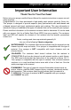
Important User Information Important User Information Thank You for Your Purchase! Before using your sprayer read this Owners Manual for complete instructions on proper use and safety warnings. Congratulations! You have purchased a high-quality paint sprayer made by Graco Inc. This sprayer is designed to provide superior spray performance with water-based and oil-based (mineral spirit-type) architectural paints and coatings.
Important Safety Information Important Safety Information The following warnings are for the setup, use, maintenance, and repair of this equipment. The exclamation point symbol alerts you to a general warning and the hazard symbols refer to procedure-specific risks. When these symbols appear in the body of this manual or on warning labels, refer back to these Warnings. Product-specific hazard symbols and warnings not covered in this section may appear throughout the body of this manual where applicable.
Important Safety Information WARNING WARNING FIRE AND EXPLOSION HAZARD SKIN INJECTION HAZARD High-pressure spray is able to inject toxins into the body and cause serious bodily injury. In the event that injection occurs, get immediate surgical treatment. Flammable fumes, such as solvent and paint fumes, in work area can ignite or explode. To help prevent fire and explosion: • Sprayer generates sparks. Do not • • spray or flush with flammable liquids.
Important Safety Information WARNING WARNING PRESSURIZED ALUMINUM PARTS HAZARD EQUIPMENT MISUSE HAZARD Misuse can cause death or serious injury. Use of fluids that are incompatible with aluminum in pressurized equipment can cause serious chemical reaction and equipment rupture. Failure to follow this warning can result in death, serious injury, or property damage. • Always wear appropriate gloves, eye • • • • • • • protection, and a respirator or mask when painting.
Component Identification Component Identification P R N A B M C J D L F Prime Pump E S G T H Spray K ti25736a A B C D E F G H J K Cup Cover FlexLiner Cup Support VacuValve Cap VacuValve Air Hole VacuValve Reservoir Strainer Spray Tip Holder Prime Pump/Spray Knob Power Cord 333394P L M N P R S T Sprayer Trigger Dual Speed Control, HIGH/LOW Switch (DS and DSP models only) Spray Tip, Black (12-inch pattern) Spray Tip, Gray (4-inch pattern) Spray Tip Guard Variable Speed Control (VSP models onl
Start Up Start Up Use only water-based or oil-based (mineral spirit-type) materials with a flash point greater than 100° F (38° C). Do not use materials which state “FLAMMABLE” on the packaging. For more information about your material, request SDS from distributor or retailer. Previously opened paint may contain dried paint or other debris. To avoid priming problems and tip clogs it is advisable to strain the paint before using. Two paint strainers are included with the sprayer.
Start Up 3. Align VacuValve on cup cover with Prime Pump/Spray knob. Push cup assembly onto sprayer and twist to lock. 6. Stop squeezing the FlexLiner and snap the VacuValve cap closed. You will hear the cap click when it is closed properly. ti23355a ti23258b 4. The VacuValve is an important part of your new sprayer. It is used to evacuate the air out of the FlexLiner. Open VacuValve cap. 7. Plug sprayer into power source. 8. Turn Prime Pump/Spray knob down to Prime Pump position.
Start Up 9. Air from pump may have entered the FlexLiner during priming. Repeat Steps 4 - 6 to ensure all air is evacuated. 10. Turn Prime Pump/Spray knob forward to spray position. Spray ti24454a • Repeat steps 2 – 6 on pages 8 – 9 to ensure all the air is evacuated from the FlexLiner. • Make certain the Prime Pump/Spray knob is in the Spray position. ti23288a 11. Make certain spray tip is in the spray position. SPRAY UNCLOG Spray ti23290a 12. You are now ready to spray.
Start Up Refilling FlexLiner If sprayer runs out of paint simply separate the cup support from the cup cover/sprayer and refill the FlexLiner. 1. Unplug sprayer from power source. 2. Separate the cup support from the cup cover/sprayer. Set the sprayer upside down on a flat surface. This will keep the wet paint in the cup cover. ti23369a 3. 333394P Follow steps 2 - 12 in Starting a New Job, page 8 procedure.
How to Spray How to Spray Take a few moments prior to spraying and review these simple tips to ensure your spraying project is a success. Dual Speed Control (Not available on all units) Spray Techniques Use a piece of scrap cardboard to practice these basic spraying techniques before you begin spraying the surface. • Hold sprayer 10 in. (25 cm) from surface and aim straight at surface. Tilting the sprayer to direct the spray angle causes an uneven finish. • Flex wrist to keep sprayer pointed straight.
How to Spray Aiming Sprayer EVEN FINISH THIN THICK Aim sprayer at bottom edge of previous stroke, overlapping each stroke by half. THIN ti23378a Rotating the spray tip guard changes the pattern to either the vertical or horizontal orientations. ti23375a Triggering Sprayer When spraying vertical corners turn spray tip guard to the horizontal orientation and move sprayer up and down. Pull trigger after starting stroke. Release trigger before end of stroke.
How to Spray Spray Pattern Quality If you see pulsations in the pattern, try the following: A good spray pattern is evenly distributed as it hits the surface. If tails persist, material may need to be thinned. If material needs to be thinned follow manufacturers recommendations.
Cleanup Cleanup 1. Disconnect power (unplug power cord). 2. Turn Prime Pump/Spray Knob down to PRIME PUMP position to relieve pressure. Use only water-based or oil-based (mineral spirit-type) materials with flash point greater than 100° F (38° C). Do not use materials which state “FLAMMABLE” on the packaging. For more information about your material, request SDS from distributor or retailer. Prime Pump Clean in a well-ventilated area. Keep a good supply of fresh air moving through the area.
Cleanup 3. Set the sprayer upside down on a flat surface. This will keep the wet paint in the cup cover. Return excess material to original container. Hold the FlexLiner in place when pouring. 8. Make certain the Prime Pump/Spray knob is in the Prime Pump position (pointed down). On models with a dual speed control switch, set speed control to HIGH. On variable speed models set speed control to 10. ti23384a ti23387a 4.
Cleanup 15. Remove spray tip and strainer, see Remove Spray Tip, page 20. Clean with appropriate cleaning fluid (water or mineral spirits). A soft brush can be used to loosen and remove dried material if needed. ti23389a 13. Remove cup assembly and discard used fluid. Dispose of used cleaning fluid properly. 14. Replace cleaning fluid and repeat steps 1- 13 until spray output is clean. ti23404a 16. Use a soft cloth to clean the cup support and cup cover.
Cleanup Cleaning VacuValve The VacuValve is an important part of your sprayer and it should be cleaned after every use. 1. Remove VacuValve cap from cup cover and clean it. 2. Clean VacuValve reservoir in lid. 3. Clean VacuValve air hole. If VacuValve air hole becomes clogged, use a paper clip to clean the hole.
Storage Storage NOTICE Failure to store sprayer with Pump Armor will result in operational problems the next time you spray. Always circulate Pump Armor through the sprayer after cleaning. Water or solvents other than mineral spirits left in the sprayer will corrode and damage the pump. ti23707b Pump Armor fluid protects the sprayer while in storage. It helps protect sprayer against freezing and corrosion when not in use. 7. With sprayer upside-down attach cup support with FlexLiner to sprayer. 1.
Common Procedures Common Procedures Installing Spray Tips Do not put your hand in front of the spray tip. Two spray tips are available for use with this sprayer. The black tip produces a 12-inch wide spray pattern. The gray tip produces a 4-inch wide spray pattern. Either spray tip may be used to spray materials that are recommended to be sprayed with a 0.015 tip size. See material container for spray tip size recommendations. Install Spray Tip 1.
Common Procedures NOTICE Spray tips must be cleaned or stored in appropriate cleaning fluid (water or mineral spirits) immediately after use to ensure material is not allowed to dry in spray tip. Failure to do so will result in damage to the spray tip. See Cleanup, page 15. Unclogging Spray Tip ti23290a SPRAY 4. UNCLOG Dual speed models: Move speed control switch to HIGH setting.
Common Procedures 7. Turn Prime Pump/Spray knob down to Prime position. Rotate spray tip back to SPRAY position. Turn Prime Pump/Spray knob forward to SPRAY position, and resume spraying. 8. If spray tip is still clogged, you may have to repeat steps 2 - 7, or replace with new spray tip assembly. See Installing Spray Tips, page 20. 2. Unscrew cup cover from the cup support. Flushing a New Sprayer This sprayer arrives from the factory with a small amount of test material in the system.
Common Procedures 4. Fill FlexLiner with water. 6. ti23258b ti23383a 5. Securely tighten cup cover onto cup support. Tighten so the arrow on the cup cover is within range of the indicator on the cup support. Align VacuValve on cup cover with Prime Pump/Spray knob. Push cup assembly onto sprayer and twist to lock. 7. Plug sprayer into power source. 8. Make certain the Prime Pump/Spray knob is in the Prime Pump position (pointed down).
Common Procedures 10. Turn Prime Pump/Spray knob forward to SPRAY position. Rotate spray tip 180 degrees to UNCLOG position. 11. While holding the sprayer upside down point the sprayer into a waste pail. Pull the trigger for three seconds. IMPORTANT! For best results, do not spray more than one cup of water through the tip while cleaning. If more flushing is needed, remove the tip from the sprayer to avoid excessive wear. 12. Sprayer is now flushed and ready for use. See Start Up, page 8.
Notes Notes 333394P 25
Replacement Parts Replacement Parts Models 16Y385, 16Y386, 17A466 13b 8 13a 19 10 12 9 9 1 5 6 24 2 22 3 15 18 7 8 20 16a 19 17 16 14 26 ti23460c 26 333394P
Replacement Parts Parts List- Models 16Y385, 16Y386, 17A466 If you have this model sprayer Ref. 1 2 3 5 6 7 8 9 10 12 All models All models All models All models All models All models All models All models All models Order Part Number Description Complete pump assembly includes 2, 3, 6, 7, 8 O-ring Filter, pump inlet O-ring Prime Pump/Spray valve includes qty. 1 of ref. 5 Kit, Prime Pump/Spray knob includes qty. 1 of ref. 8 Screw, T-15 (torque 8-10 in-lb / 0.9-1.
Replacement Parts Replacement Parts Model 17D889 27 13 29 8 19 12 10 9 9 1 5 24 6 8 19 2 18 15 22 7 3 16a 20 17 16 28 14 26 ti25730c 28 333394P
Replacement Parts Parts List- Model 17D889 If you have this model sprayer Ref. 1 2 3 5 6 7 8 9 10 12 All models All models All models All models All models All models All models All models All models 17D889 Order Part Number Description 17B415 16Y425 16W849 117059 17A402 17A221 119236 17A223 16X880 17F068 Complete pump assembly includes 2, 3, 6, 7, 8 O-ring Filter, pump inlet O-ring Prime Pump/Spray valve includes qty. 1 of ref. 5 Kit, Prime Pump/Spray knob includes qty. 1 of ref.
Troubleshooting Troubleshooting Have a Question? Call toll-free: Check everything in this Troubleshooting Table before you bring the sprayer to an authorized service center. 1-888-541-9788 Or visit us at: www.magnum.graco.com/support Sprayer Diagnostics Problem ti24021a Cause Solution Sprayer makes no sound Power supply. when trigger is pulled Motor has overheated. Verify power to sprayer. Wait 20-30 minutes for motor to cool. Electronic control failure. Replace electronic control.
Troubleshooting Problem Cause Solution On models with a dual speed control switch, set speed control switch to HIGH. On variable speed models, increase speed until unit sprays. No or low material in material cup. Refill FlexLiner with material and prime the pump. See Refilling FlexLiner, page 11. See Unclogging Spray Tip, Sprayer sprays with poor Spray tip is partially clogged. page 21. results Spray tip is not in correct position Rotate spray tip to SPRAY position.
Troubleshooting Spray Pattern Diagnostics Problem Cause Spray pattern is pulsating: Slow speed of movement. Spray tip is clogged. Unclog spray tip or clean spray tip see Unclogging Spray Tip, page 21. On models with a dual speed control switch, set speed control to HIGH. On variable speed models, increase speed until desired pattern is achieved. Hold sprayer farther away from surface. Switch to black (12”) spray tip. See Installing Spray Tips, page 20.
Troubleshooting Problem Cause Spray pattern is too narrow: ti15523a ti15523a Sprayer is too close to target surface. Incorrect spray tip for application of material. Spray tip is worn or damaged. Sprayer is too far away from target surface. Incorrect spray tip for application of material. Spray pattern is too wide: Solution Move sprayer away from surface 10 in. (25 cm) Install different size spray tip. See Installing Spray Tips, page 20. Replace spray tip. See Installing Spray Tips, page 20.
Technical Data Technical Data Hand-Held Sprayer U.S. Max Working Pressure Maximum Amperage Weight TrueCoat 360, 360 DS/DSP TrueCoat 360 VSP Dimensions: Length (All models) Width (All models) Height 360, 360 DS/DSP Height 360 VSP Storage Temperature Range Operating Temperature Range Storage Humidity Range Power Cord Electrical Power Requirement Duty Cycle Maximum tip orifice Metric 1500 psi 2.5 Amps 2.5 Amps 3.5 lb (18 in.cord) 3.75 lb (18 in.cord) 1.6 kg (45 cm cord) 1.7 kg (45 cm cord) 12.50 in.
Graco Limited Warranty Graco Limited Warranty Graco warrants to the original purchaser that this product will be free from defects in material and workmanship for one (1) year from the date of purchase when operated and maintained in accordance with Graco's written recommendations and instructions. This product is designed and intended for personal, non-income producing, household purposes only.
All written and visual data contained in this document reflects the latest product information available at the time of publication. Graco reserves the right to make changes at any time without notice. Original instructions. This manual contains English. MM 333394 Graco Headquarters: Minneapolis International Offices: Belgium, China, Japan, Korea GRACO INC. AND SUBSIDIARIES • P.O. BOX 1441 • MINNEAPOLIS MN 55440-1441 • USA Copyright 2014, Graco Inc.