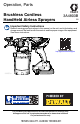
Operation, Parts Brushless Cordless HandHeld Airless Sprayers 3A4803B EN Important Safety Instructions Read all warnings and instructions in this manual, on the unit, and in the battery and charger manual. Be familiar with the controls and the proper usage of the equipment. Save these instructions. Operational video. http://graco.com/hhsupport ti30553a 844-241-9499 For portable spray applications of architectural paints and coatings only.
Contents Contents Models – Cordless Airless HandHelds . . . . . . . . . . . . . . . . . . . . . . . . . . . . . . 3 Important User Information . . . . . . . . . . . . . . . . . . . . . . . . . . . . . . . . . . . . . . . 4 General Power Tool Safety Information . . . . . . . . . . . . . . . . . . . . . . . . . . . . . 5 Warnings . . . . . . . . . . . . . . . . . . . . . . . . . . . . . . . . . . . . . . . . . . . . . . . . . . . . . . 7 Know Your Sprayer . . . . . . . . . . . . . . . . . . . . . . . . . . .
Models – Cordless Airless HandHelds Models – Cordless Airless HandHelds Model 17M367 17P928 17N222 17P929 110474 Certified to CAN/CSA C22.2 No. 68 Conforms to UL 1450 17N223 Sprayer Name Ultra MAX Ultimate MX TC PRO PLUS Charger Voltage Tip Family 120V * 120V * FFLPxxx 120V TCPxxx 17P258 17M368 17P930 17P931 17N224 17M370 17P257 17N225 Tip Size 0.008 – 0.016 in. (0.20 – 0.
Important User Information Important User Information Thank You for Your Purchase! Before using your sprayer read this Owners Manual for complete instructions on proper use and safety warnings. Congratulations! You have purchased a high-quality paint sprayer made by Graco Inc. This sprayer is designed to provide superior spray performance with all architectural paints and coatings. This user information is intended to help you understand the types of materials that can be used with your sprayer.
General Power Tool Safety Information General Power Tool Safety Information Read all safety warnings and all instructions. Failure to follow the warnings and instructions may result in electric shock, fire and/or serious injury. Save all warnings and instructions for future reference. The term “power tool” in the warnings refers to your mains-operated power tool. Work Area Safety • Keep work area clean and well lit. Cluttered or dark areas invite accidents.
General Power Tool Safety Information Power Tool Use and Care • Do not force the power tool. Use the correct power tool for your application. The correct power tool will do the job better and safer at the rate for which it was designed. • Do not use the power tool if the switch does not turn it on and off. Any power tool that cannot be controlled with the switch is dangerous and must be repaired.
Warnings Warnings The following warnings are for the setup, use, maintenance, and repair of this equipment. The exclamation point symbol alerts you to a general warning and the hazard symbols refer to procedure-specific risks. When these symbols appear in the body of this manual or on warning labels, refer back to these Warnings. Product-specific hazard symbols and warnings not covered in this section may appear throughout the body of this manual where applicable.
Warnings FIRE AND EXPLOSION HAZARD Flammable fumes, such as solvent and paint fumes, in work area can ignite or explode. To help prevent fire and explosion: • Do not spray flammable or combustible liquids in a confined area. • Keep spray area well-ventilated. Keep a good supply of fresh air moving through the area. • Paint or solvent flowing through the sprayer is able to result in static electricity. Static electricity creates a risk of fire or explosion in the presence of paint or solvent fumes.
Warnings EQUIPMENT MISUSE HAZARD Misuse can cause death or serious injury. • Always wear appropriate gloves, eye protection, and a respirator or mask when painting. • Do not operate or spray near children. Keep children away from equipment at all times. • Do not overreach or stand on an unstable support. Keep effective footing and balance at all times. • Stay alert and watch what you are doing. • Do not operate the unit when fatigued or under the influence of drugs or alcohol.
Know Your Sprayer Know Your Sprayer N P J PRIME PUMP ti30555a SPRAY E D F L T A B C T G A B C D E F G H 10 Cup Cover FlexLiner Cup Support VacuValve Cap VacuValve Air Hole VacuValve Reservoir Pump Filter Ground Plug and Spool M H J K L M N P T K Prime Pump/Spray Knob Battery Sprayer Trigger Speed Control, ProControl II Spray Tip.
Start Up Start Up Flammable fumes (such as solvent and paint fumes) in work area can ignite or explode. See GROUNDING INSTRUCTIONS, page 7. Do not spray flammable or combustible liquids in a confined area. Keep spray area well-ventilated. Keep a good supply of fresh air moving through the area. NOTICE Do NOT shake materials to be used with this sprayer. Some fine finish lacquers and enamels trap air when shaken, which can affect sprayer performance.
Start Up Starting a New Job 1. Install FlexLiner in the cup support. When spraying flammable or combustible materials: • Move entire sprayer to a well-ventilated area and away from flammable or combustible materials, including paints and solvents when refilling. • Keep material containers covered between cup refills. If you are using the sprayer for the very first time, see Flush a New Sprayer, page 25. Strain the Paint ti23361a Previously opened paint may contain dried paint or other debris.
Start Up 4. The VacuValve is an important part of your new sprayer. It is used to evacuate the air out of the FlexLiner. Open VacuValve cap. 7. Install battery onto sprayer. 8. Turn Prime Pump/Spray knob down to Prime Pump position. To fill sprayer with fluid, point sprayer into a waste area and hold the trigger in for 3 – 10 seconds. ti30557a ti29721a 5. Tilt the sprayer so the VacuValve is the highest point, causing any air in the FlexLiner to rise to the VacuValve.
Start Up If sprayer does not spray, try one of the steps below: • • Make certain there is only one FlexLiner in cup support. It is possible for two liners to nest tightly together and appear as only one. Refilling FlexLiner • Make certain the cup cover is properly threaded to the cup support. If threads are visible below the cup cover when tight, then the cover is cross-threaded. Fully remove the cup cover and reinstall to the cup support so no threads are visible when tight. Replace VacuValve cap.
How to Spray How to Spray Speed Control Take a few moments prior to spraying and review these simple tips to ensure your spraying project is a success. NOTE: For proper sprayer operation use only a tip from the same tip family that came with your sprayer. Sprayer Name Tip Family Tip Part No. Ultra FFLP FFLPxxx Ultimate FFLP FFLPxxx TC Pro TCP TCPxxx ti29773a The speed control allows for infinite pressure adjustment.
How to Spray Triggering Sprayer 12 in. (30 cm) Pull trigger after starting stroke. Release trigger before end of stroke. Sprayer must be moving when trigger is pulled and released. EVEN FINISH ti30015a Aiming Sprayer THICK Aim sprayer at bottom edge of previous stroke, overlapping each stroke by half. UNEVEN FINISH THIN ti29743a EVEN FINISH ti29745a THICK THIN ti29744a THIN Rotating the spray tip guard changes the pattern to either the vertical or horizontal orientations.
How to Spray When spraying vertical corners turn spray tip guard to the horizontal orientation and move sprayer up and down. Clear Tip Clog In the event that particles or debris clog the spray tip, this sprayer is designed with a reversible spray tip that quickly and easily clears the particles without disassembling the sprayer. See for Strain the Paint, page 12 for additional information. 1. To unclog spray tip, turn Prime Pump/Spray knob down to Prime Pump position.
How to Spray 4. Aim sprayer at waste area, turn Prime Pump/Spray knob forward to spray position. Pull trigger to clear clog. 5. Turn Prime Pump/Spray knob down to Prime position. Rotate spray tip back to SPRAY position. Turn Prime Pump/Spray knob forward to SPRAY position, and resume spraying. 6. If spray tip is still clogged, you may have to repeat steps 1 – 5, or replace with new spray tip assembly. See Spray Tip Installation, page 24.
Cleanup Cleanup Cleaning your sprayer properly and after every spray job is of the utmost importance! Proper care and maintenance will make your paint sprayer last and work for you trouble free. See Cleaning Fluid Compatibility, page 28 and Static Grounding Instructions (Oil-Based or flammable materials), page 28 for additional information when using oil-based or flammable materials. 1. Turn Prime Pump/Spray knob to Prime Pump to relieve pressure. 2. Open the vacuvalve to allow air into the FlexLiner.
Cleanup 4. Set the sprayer upside down on a flat surface. This will keep the wet paint in the cup cover. Return excess material to original container. Hold the FlexLiner in place when pouring. ti29759a 5. You can either dispose of the used FlexLiner and install a new FlexLiner or clean a used FlexLiner. ti29756b 8. To clean the cup cover and pump filter shake the entire sprayer for ten seconds. To avoid fire and explosion do not spray solvents through the spray tip.
Cleanup 9. Make certain the Prime Pump/Spray knob is in the Prime Pump position (pointed down). Set speed control to 10. b. Reverse the spray tip to UNCLOG position, pull the trigger for five seconds. Release the trigger. ti29766a 10. Turn the sprayer upside down and point the sprayer into a waste pail. Pull the trigger for 15 seconds. ti30232a 13. If second spray tip was used, remove cleaned spray tip from spray tip guard and install second spray tip. See Spray Tip Installation, page 24.
Cleanup 16. Remove spray tip, spray tip guard, and pump filter. Clean with appropriate cleaning fluid (water or mineral spirits). A soft brush can be used to loosen and remove dried material if needed. This sprayer is equipped with a static wick that reduces the build-up of static charge to reduce the risk of fire and explosion. KEEP THIS SURFACE CLEAN OF OVERSPRAY. ti30635a Cleaning VacuValve ti29769a 17. Use a soft cloth to clean the cup support and cup cover.
Storage Storage With proper storage, the sprayer will be ready to use the next time it is needed. NOTICE Failure to store sprayer with Pump Armor can result in operational problems the next time you spray. Always circulate Pump Armor through the sprayer after cleaning. Water or solvents other than mineral spirits left in the sprayer will corrode and damage the pump. ti29770a Pump Armor fluid protects the sprayer while in storage. It helps protect sprayer against freezing and corrosion when not in use. 6.
Common Procedures Common Procedures Spray Tip Installation 3. Insert Spray Tip. Spray tip must be pushed all the way into the tip guard. To avoid serious injury from skin injection do not put your hand in front of the spray tip when installing or removing the spray tip and tip guard. To prevent spray tip leaks make certain spray tip and tip guard are installed properly. 1. Perform Pressure Relief Procedure, page 11. 2. Use spray tip (A) to insert seal (B) into tip guard (C).
Common Procedures Flush a New Sprayer 3. Make certain FlexLiner is in the cup support. Always start with a fully charged battery. Refer to battery and charger information provided. This sprayer arrives from the factory with a small amount of test material in the system. It is important that you flush this material from the sprayer before using it for the first time.
Common Procedures 5. Securely tighten cup cover onto cup support. 9. Turn the sprayer upside down and point the sprayer into a waste pail. Pull the trigger for three seconds. 10. Turn Prime Pump/Spray knob forward to SPRAY position. Rotate spray tip 180 degrees to UNCLOG position. ti29719a Align VacuValve on cup cover with Prime Pump/Spray knob. Push cup assembly onto sprayer and twist to lock. SPRAY UNCLOG ti29740a 6. ti29739a 11.
Reference Reference Fan Width Spray Tip Selection Fan width is the size of the spray pattern, which determines the area covered with each stroke. Selecting Tip Size Hints: Spray tips come in a variety of hole sizes for spraying a range of fluids. Your sprayer includes a tip for use in most paint spraying applications. Use the coatings table on page 15 to determine the range of recommended tip hole sizes for each fluid type. If you need a tip other than the one supplied, see the How to Spray, page 15.
Reference Cleaning Fluid Compatibility Oil-Based or Flammable or Water-Based Materials • When spraying water-based materials, flush the system thoroughly with water. • When spraying oil-based or flammable materials, flush the system thoroughly with mineral spirits or compatible, flushing solvent. • To spray water-based materials after spraying oil-based or flammable materials, flush the system thoroughly with water first.
Maintenance Maintenance Routine maintenance is important to ensure proper operation of your sprayer. Move sprayer to a well-ventilated area and away from flammable or combustible materials, including paints and solvents. Activity Interval Inspect pump filter. Daily or each time you spray Inspect enclosure vents for blockage. Daily or each time you spray Inspect pump inlet holes located under pump filter for blockage.
Maintenance Grounding Wire Repair If the grounding wire breaks at the spool end, perform the following steps: 1. Unwind wire from grounding spool and use a flat screwdriver to pry apart the grounding spool. ti30561a 3. Snap the grounding spool back together. If the grounding wire breaks at the grounding plug, perform the following steps: 1. ti30560a 2. Pull rubber boot off of wire at grounding plug and slide boot over grounding wire. Loosen screw on terminal and remove broken wire.
Notes Notes 3A4803B 31
Replacement Parts Replacement Parts 12 34 38 1 31 54 9 3 51 30 25 4 37 1 11 7 4 4b 50 3 4a 37a 36 2 18 19 29 13 16 14 15 52 ti30563a Ref. 32 Torque Ref. Torque 1 10 in-lb (1.1 N•m) 4 55-65 in-lb (6.2 - 7.3 N•m) 2 8-10 in-lb (0.9 - 1.1 N•m) 7 5-7 in-lb (0.6 - 0.8 N•m) 3 10-15 in-lb (1.1 - 1.
Replacement Parts Parts List Ref.
Replacement Parts Ref. Sprayer Name Part # 17P474 38 * 17P557 17P556 17P558 17P475 39 * 17P560 40 50 51 --- 17P559 17P561 17M883 118594 117724 24D386 52 All All All 17N222, 17N223, 17M367, 17P928, 17P929 All Description Li-ion Compact Battery Pack DEWALT Models; 17M367, 17N222, 17N223. Models; 17P928 and 17P929 requires this battery. Models; 17P257, 17P258, 17M368, 17M370 requires this battery. Models; 17N930 and 17P931 ships without the battery. Model; 17N224 requires this battery.
Troubleshooting Troubleshooting 844-241-9499 Check everything in this Troubleshooting Table before you bring the sprayer to an authorized service center. Sprayer Diagnostics Problem Cause Sprayer makes no sound Diagnostic light blinks two times when trigger is pulled when trigger is pulled. Indicates incorrect voltage. Diagnostic light blinks three times when trigger is pulled. Indicates battery temperature is too hot or cold. Diagnostic light blinks four times when trigger is pulled.
Troubleshooting Problem Cause Solution Prime the pump. See Starting a New Job, page 12. Make certain there is only one FlexLiner in the cup support. Make certain the cup cover is properly threaded to the cup support. If threads are visible below the cup cover when tight, fully remove and reinstall to the cup support so no threads are visible when tight. Make certain the cup cover is tightened to cup support so the arrow on cup cover is within range of indicator on cup support.
Troubleshooting Problem Cause Solution See Clear Tip Clog, page 17. Rotate spray tip to SPRAY position. Incorrect spray tip for application of Install different size spray tip. See material. Tip and Pressure Selection, page 15. Spray tip is worn or damaged Replace spray tip. See Spray Tip Installation, page 24. Material being sprayed is aerated Do NOT shake material. Stir the because it was shaken. material or check the manufacturer’s recommendation for the material being sprayed.
Troubleshooting Spray Pattern Diagnostics Problem Spray pattern is uneven: Cause Operator is moving too fast while spraying. Spray tip is clogged. Material difficult to atomize. Outlet valves are dirty or worn. Spray pattern has tails: Pump has reached the end of its life. Speed control is set too low. Material may need to be thinned. Incorrect spray tip for application of material. Spray pattern has dripping/sagging: Spray pattern is too narrow: Material not compatible with sprayer.
Troubleshooting Problem Spray pattern is too wide: Spray pattern “spits” at the beginning or end of pattern: Spray tip continues to drip or ooze material after trigger is released: Cause Move sprayer closer to surface. Excess material has accumulated on spray tip guard assembly or spray tip is partially clogged. Spray tip not inserted completely into spray tip guard. Spray tip is worn. Clean spray tip guard. See Clear Tip Clog, page 17. Sprayer is dirty Front valve has reached the end of its life.
Technical Specifications Technical Specifications Brushless Cordless HandHeld Sprayer Max Working Pressure Weight Dimensions: Length Width Height Storage Temperature Range Operating Temperature Range Storage Humidity Range Sound Pressure Level Sound Power Level † Vibration level (Measured in accordance with EN 50580:2012) Charger Power Source 17N222, 17N224, 17N223, 17M367, 17P928, 17P929 17M368, 17M370, 17N225, 17P257, 17P258, 17P930, 17P931 Battery Voltage (DC) Maximum tip orifice U.S.
Graco Limited Warranty Graco Limited Warranty Graco warrants all equipment referenced in this document which is manufactured by Graco and bearing its name to be free from defects in material and workmanship on the date of sale to the original purchaser for use. With the exception of any special, extended, or limited warranty published by Graco, Graco will, for a period of twelve months from the date of sale, repair or replace any part of the equipment determined by Graco to be defective.
Graco Limited Warranty Graco Information For the latest information about Graco products, visit www.graco.com. For patent information, see www.graco.com/patents. TO PLACE AN ORDER, contact your Graco distributor or call 1-888-541-9788 to identify the nearest distributor.
Notes Notes 3A4803B 43
DEWALT®and the DEWALT Logo are trademarks of DEWALT Industrial Tool Co. and are used under license All written and visual data contained in this document reflects the latest product information available at the time of publication. Graco reserves the right to make changes at any time without notice. Original instructions. This manual contains English. MM 3A4803 Graco Headquarters: Minneapolis International Offices: Belgium, China, Japan, Korea GRACO INC. AND SUBSIDIARIES • P.O.