Operation LineLazer IV 250SPS Self-Propelled Line Striper 3A2090A EN For the application of line striping materials. For professional use only. For outdoor use only. Not for use in hazardous locations or explosive atmospheres. Maximum Operating Speed: 10 mph (16 kph) Maximum Operating Pressure: 3300 psi (22.8 MPa, 228 bar) IMPORTANT SAFETY INSTRUCTIONS Read all warnings and instructions in this manual and the engine manual. Save these instructions.
Table of Contents Warnings . . . . . . . . . . . . . . . . . . . . . . . . . . . . . . . . . 3 Component Identification (Sprayer) . . . . . . . . . . . 6 Component Identification (Controls) . . . . . . . . . . . 7 Grounding Procedure (For Flammable Materials Only) . . . . . . . . . . . . 8 Pressure Relief Procedure . . . . . . . . . . . . . . . . . . . 8 Setup/Startup . . . . . . . . . . . . . . . . . . . . . . . . . . . . . . 9 SwitchTip and Guard Assembly . . . . . . . . . . . . 11 Gun Placement . . . . .
Warnings Warnings The following warnings are for the setup, use, grounding, maintenance, and repair of this equipment. The exclamation point symbol alerts you to a general warning and the hazard symbols refer to procedure-specific risks. When these symbols appear in the body of this manual or on warning labels, refer back to these Warnings. Product-specific hazard symbols and warnings not covered in this section may appear throughout the body of this manual where applicable.
Warnings WARNING ENTANGLEMENT HAZARD Rotating parts can cause serious injury. • Keep clear of moving parts. • Do not operate equipment with protective guards or covers removed. • Do not wear loose clothing, jewelry or long hair while operating equipment. • Equipment can start without warning. Before checking, moving, or servicing equipment, follow the Pressure Relief Procedure and disconnect all power sources. MOVING PARTS HAZARD Moving parts can pinch, cut or amputate fingers and other body parts.
Warnings WARNING BATTERY SAFETY The battery may leak, explode, cause burns, or cause an explosion if mishandled. • Only use the battery type specified for use with the equipment. See Technical Data. • Battery maintenance must only be performed or supervised by personnel knowledgeable of batteries and the required precautions. Keep unauthorized personnel away from battery. • Do not dispose of battery in fire. The battery is capable of exploding. • Follow local ordinances and/or regulations for disposal.
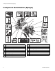
Component Identification (Sprayer) Component Identification (Sprayer) 1. 16. 15. 14. 11. 17. 2. 13. 12. 10. 3. F OF ON 9. 8. 4. 5. 7. 6.
Component Identification (Controls) Component Identification (Controls) 5. 4. 3. 6. 2. 7. 1. 1 on off 2 8. 1 2 9. 10. 11.
Grounding Procedure (For Flammable Materials Only) Grounding Procedure Pressure Relief Procedure (For Flammable Materials Only) This equipment must be grounded to reduce the risk of static sparking. Static sparking can cause fumes to ignite or explode. Grounding provides an escape wire for the electric current. This equipment stays pressurized until pressure is manually relieved.
Setup/Startup Setup/Startup 6. If removed, install strainer. This equipment stays pressurized until pressure is manually relieved. To help prevent serious injury from pressurized fluid, such as skin injection, splashing fluid and moving parts, follow the Pressure Relief Procedure when you stop spraying and before cleaning, checking, or servicing the equipment. 1. Perform Grounding Procedure (page 8) if using flammable materials. ti3430a 7. Turn prime valve down.
Setup/Startup f. 10. Start engine: After engine starts, move choke to open. a. Move fuel valve to open. ti3312a b. ti18563a Move choke to closed. 11. Set main power switch ON. ti18552a 12. Set pump valve ON (pump is now active). ti18561a c. Set throttle to fast. ti6471a ti18568a 13. Set throttle to desired setting. d. Set engine switch ON. OFF ON ti18568a ti3315a e. Pull starter cord.
Setup/Startup 14. Increase pressure control enough to start pump. Allow fluid to circulate for 15 seconds. ti3442a 19. Trigger gun again into flushing fluid pail until paint appears. Assemble tip and guard. 15 SEC. 15. Turn pressure down, turn prime valve horizontal. Disengage gun trigger safety. ti6472a 20. Repeat steps 6 - 10 on second gun for 2-gun models. 3304c ti3441a 16. Hold gun against grounded metal flushing pail. Trigger gun and increase fluid pressure slowly until pump runs smoothly.
Gun Placement Gun Placement Install Gun 1. Insert gun into gun holder. Tighten clamp. 3. Use the Gun Selector Switches to determine which guns are active. Each gun selector switch has 3 positions: continuous line, OFF, and programmed line pattern. Programmed line pattern OFF position disengages gun Continuous line ti18969a ti18570a 2 Examples: Position Gun 1 2. Position gun: up/down, forward/reverse, left/right. See Gun Positions Chart, page 17 for examples.
Gun Placement Gun Arm Mounts 3. Slide gun arm assembly into desired gun arm mounting slot. This unit is equipped with front and rear gun arm mounts. ti18980a 4. Tighten gun arm knob into gun arm mounting slot. ti18556a ti18974a NOTICE ti18555a Make sure all hoses, cables, and wires are properly routed through brackets and do NOT rub on tire. Contact with tire will result in damaged hoses, cables, and wires. Change Gun Position (Front and Back) 1.
Gun Placement 3. Loosen gun mounting wing nut and remove gun mount. 2. Install gun mount onto gun arm assembly and tighten gun mount wing nut. ti18978a ti18979a ti18984a 3. Tighten gun arm knob into gun arm mounting slot. ti18985a 4. Slide gun arm assembly out from gun arm mounting slot. ti18976a ti18983a 4. Install guns into gun mounts. Installation 1. Slide gun arm assembly into gun arm mounting slot. ti18986a NOTE: Make sure all hoses, cables, and wires are properly routed through brackets.
Gun Placement Gun Cable Adjustment 3. Install cable end onto trigger plate pin and install clip. Adjusting the gun cable will increase or decrease the gap between the trigger plate and the gun trigger. To adjust trigger gap, perform the steps below. + ti18987a ti18998a 1. Use wrench to loosen locking nut on cable adjuster. 4. Route cable around unit and up through cable holes behind hose mount. 2. Loosen or tighten adjuster until desired result is achieved.
Gun Placement Change Trigger Position Removal Installation 1. Remove both hand grips from handle bar (spraying compressed air into end of handle grip works well for this). 1. Route trigger wire to other side of handle bar. Make sure wire is routed behind steering column, through wire slot on steering plate, and into wire clamp on handle bar. ti18993a ti18988a 2. Install trigger assembly onto desired handle bar. 2. Use an allen wrench to loosen bolt on trigger mounting clamp. ti18991a 3.
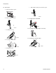
Gun Placement Gun Positions Chart 1 4 2 3 5 3A2090A Operation 1 One line 2 One line up to 24 in. (61 cm) wide.
Driving Instructions Driving Instructions To turn right and left: Turn the handle bar right or left to steer the LineStriper. Perform Startup, page 9. Use the handle bars of the LineStriper to control all motion during operation. In addition to steering the LineStriper, the handle bars also control forward and reverse movement by pulling the forward/reverse control lever. ti17518a NOTE: Make sure wheel motor bypass valve is engaged (see page 19).
Driving Instructions Drive Engagement 3. If striper arcs to the left, turn adjuster screw counter-clockwise. The wheel motor bypass valve allows the operator to disengage the wheel tension and push the unit around. Rotate one complete turn counter-clockwise to disengage. ti18591a 4. Test-drive the striper. Repeat steps 2 and 3 until striper drives straight. Tighten two bolts on wheel alignment plate to lock the new wheel setting.
Driving Instructions Platform Storage Position Front Pad Adjustment 1. Raise stand and pin self-locks. 1. Loosen four bolts. 2. Slide pad up or down to desired position. 4 bolts ti18560a ti19006a 2. To lower stand, pull pin and lower stand. 3. Tighten four bolts.
Smart Control Overview Smart Control Overview Quick Guide 3A2090A Operation 21
Smart Control Operation Smart Control Operation Initial Setup Calibration 1. Select appropriate language. 1. Check tire pressure and fill if necessary. 2. Rotate calibration bar. ti19024a ENG = English SPA = Spanish FRE = French DEU = German ti18713a NOTE: Languages can also be changed later. 2. Select appropriate units of measure. 3. Insert calibration bar face down.
Smart Control Operation 6. Press SETUP twice to move to CALIBRATION & UNITS display. Set TRAVEL DISTANCE to 25 ft. Longer distances ensure better accuracy, depending on conditions. 10. Stop when calibration bar rear edge aligns with 26-ft. on steel tape (25-ft. distance). \ $ % !" "# 26 FT &'( ) ti9915b ti10022a 11. Push gun trigger control to complete calibration. ti18564a % * + # #,!# / 12.
Smart Control Operation Change Units or Language 1. Press SETUP twice to move to CALIBRATION & UNITS display. Select CHANGE UNITS. 2. While in CHANGE UNITS display, press CHANGE to change units or NEXT to move to the next unit of measure. Press SETUP to exit CHANGE UNITS mode.
Smart Control Operation Operation in Manual Mode Operation in Automatic Mode Preset Skip Patterns ,:B,D G" $ % !" "# &'( ) ti9915b 1. Make sure engine is running and main power switch is on. 1. In the AUTOMATIC MODE, the striper is equipped with Preset Skip Patterns. To select a preset skip pattern, press MODE button to move to AUTOMATIC MODE. ,:B,D G" $ % !" "# &'( ) ti9915b 2.
Smart Control Operation Advanced: Preset Skip Patterns 1. A Preset Skip Pattern can be modified for a custom pattern. From AUTO MODE press SETUP key to get preset patterns. + B# 8,# 9 G" ? ' > + 8 H @ > I > 3. Use EDIT arrows to change the PAINT line length. Use SELECT arrows to scroll down to SPACE length. Use EDIT arrows to change the SPACE length. Press SETUP key to save and return to AUTOMATIC MODE display. ROAD PRE-SETS >>PAINT 10.0<< SPACE 30.
Smart Control Operation Parking Layout Mode Advanced: Parking Calc NOTE: Please use the 286111 tip provided with striper for parking lot layout work. For best performance set pressure to 1000 psi (68.9 bar, 6.89 MPa) and reverse tip. 1. Press SETUP and move to PARKING CALC. The striper divides the stall size into the measurement taken here to determine the number of stalls that can be striped in this space.
Smart Control Operation Angle Stalls 4. Measure and mark the offset distance for the first stall. 1. Angle stalls require the operator to input stall angle and depth. The Auto-Layout System calculates the offset distance based on this input. 5. Press SETUP two times to save angled stall dot spacing to PARKING LAYOUT MODE. 2. From PARKING LAYOUT MODE press SETUP two times for ANGLE CALC.
Smart Control Operation Marker Mode 1. Press the MODE key to select Parking Layout Mode. 2. Press SETUP three times to select Marker Layout Mode. ? Automatic marker layout example shows typical lane line layout for reflective markers. Set space sizes up to 8 consecutive measurements. By leaving zeros in any space, AutoLayout will skip to the next measurement in a continuous loop.
Smart Control Operation Measure Mode Machine Information 1. Press SETUP once from Manual Mode display. 1. Press SETUP button three times from Manual Mode display.
Cleanup Cleanup This equipment stays pressurized until pressure is manually relieved. To help prevent serious injury from pressurized fluid, such as skin injection, splashing fluid and moving parts, follow the Pressure Relief Procedure when you stop spraying and before cleaning, checking, or servicing the equipment. 5. Place siphon tube set in grounded metal pail partially filled with flushing fluid. Attach ground wire to true earth ground.
Hydraulic Oil/Filter Change Hydraulic Oil/Filter Change Removal This equipment stays pressurized until pressure is manually relieved. To help prevent serious injury from pressurized fluid, such as skin injection, splashing fluid and moving parts, follow the Pressure Relief Procedure when you stop spraying and before cleaning, checking, or servicing the equipment. 227 1. Relieve pressure, page 8. 2. Place drip pan or rags under sprayer to catch hydraulic oil that drains out. 3. Remove drain plug.
Technical Specifications Technical Specifications LineLazer IV 250SPS (Models 24F307, 24K960, 24K961, 24K962, 24M608) U.S. Metric Height (with handle bar down) Unpackaged - 47.25 in. Packaged - 54.25 in. Unpackaged - 120.0 cm Packaged - 137.8 cm Width Unpackaged - 33.0 in. Packaged - 40.0 in. Unpackaged - 83.8 cm Packaged - 101.6 cm Length (with platform down) Unpackaged - 73.5 in. Packaged - 78.0 in. Unpackaged - 186.7 cm Packaged - 198.1 cm Weight Unpackaged - 627.0 lb Packaged - 730.
Notes Notes 34 3A2090A Operation
Notes Notes 3A2090A Operation 35
Graco Standard Warranty Graco warrants all equipment referenced in this document which is manufactured by Graco and bearing its name to be free from defects in material and workmanship on the date of sale to the original purchaser for use. With the exception of any special, extended, or limited warranty published by Graco, Graco will, for a period of twelve months from the date of sale, repair or replace any part of the equipment determined by Graco to be defective.