Operation, Parts Air Compressor & Hopper Guns (Gravity-Fed & Pressurized) 3A5725C For spray application of water-based architectural and texture coatings. Air compressor for supplying air to hopper guns only. Not approved for use in explosive atmospheres or hazardous (classified) locations. For professional use only. See page 3 for model information. 5 psi (0.03 MPa, 0.3 bar) Hopper Maximum Working Air Pressure 60 psi (0.41 MPa, 4.1 bar) Compressor Maximum Working Air Pressure 100 psi (0.69 MPa, 6.
Table of Contents Table of Contents Models . . . . . . . . . . . . . . . . . . . . . . . . . . . . . . . . . . . . . . . . . . . . . . . . . . . . . . . . . . . . . . 3 Warnings . . . . . . . . . . . . . . . . . . . . . . . . . . . . . . . . . . . . . . . . . . . . . . . . . . . . . . . . . . . . 4 Component Identification . . . . . . . . . . . . . . . . . . . . . . . . . . . . . . . . . . . . . . . . . . . . . . . 7 25D496 - Pressurized Hopper Gun . . . . . . . . . . . . . . . . . . . . . . . . . . . . . .
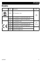
Models Models Model Description 25D490 Air Compressor, bare VAC 120 USA 3A5725C 25D492 Air Compressor, w/ pressurized hopper gun 25D494 Air Compressor, w/ gravity-fed hopper gun 25D491 Air Compressor, bare 25D493 Air Compressor, w/ pressurized hopper gun 25D495 Air Compressor, w/ gravity-fed hopper gun 25D496 Pressurized Hopper Gun 25D497 Gravity-Fed Hopper Gun 230 Europe 3
Warnings Warnings The following warnings are for the setup, use, grounding, maintenance, and repair of this equipment. The exclamation point symbol alerts you to a general warning and the hazard symbols refer to procedure-specific risks. When these symbols appear in the body of this manual or on warning labels, refer back to these Warnings. Product-specific hazard symbols and warnings not covered in this section may appear throughout the body of this manual where applicable.
Warnings ELECTRIC SHOCK HAZARD This equipment must be grounded. Improper grounding, setup, or usage of the system can cause electric shock. • Turn off and disconnect power cord before servicing equipment. • Connect only to grounded electrical outlets. • Use only 3-wire extension cords. • Ensure ground prongs are intact on power and extension cords. • Do not expose to rain. Store indoors.
Warnings PLASTIC PARTS CLEANING SOLVENT HAZARD Many cleaning solvents can degrade plastic parts and cause them to fail, which could cause serious injury or property damage. • Use only compatible solvents to clean plastic structural or pressure-containing parts. • See Technical Specifications in all equipment manuals for materials of construction. Consult the solvent manufacturer for information and recommendations about compatibility.
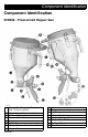
Component Identification Component Identification 25D496 - Pressurized Hopper Gun A B C D E F G H Material Flow Regulator (Push down to lock.
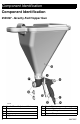
Component Identification Component Identification 25D497 - Gravity-Fed Hopper Gun A B C D E 8 Needle Travel Adjustment Knob Hopper Air Valve Trigger Trigger Lock F G H J Nozzle Retainer Material Nozzles (4mm, 6mm & 8mm) Air Hose Fitting Hopper Clamp 3A5725C
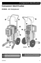
Component Identification Component Identification 25D490 - Air Compressor A B C Power Switch Air Hose Fitting Power Cord 3A5725C D E Cart Handle Hose/Power Cord Storage 9
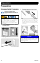
Preparation Preparation Pressure Relief Procedure 3. Disconnect spray gun from air hose. 4. Open pressure relief valve on gun by pressing button (pressurized gun only). Aim gun into waste bucket and trigger the gun until all air and material pressure is relieved. Follow the Pressure Relief Procedure whenever you see this symbol. The hopper is pressurized. To reduce the risk of splashing from pressurized fluid, always follow the Pressure Relief Procedure before removing the hopper from the gun. 1.
Preparation Grounding Extension Cords NOTE: Avoid use of extension cords if possible. The equipment must be grounded to reduce the risk of static sparking and electric shock. An electric or static spark can cause fumes to ignite or explode. An improper ground can cause electric shock. A good ground provides an escape wire for the electric current. This product is equipped with a cord that has a grounding wire and an appropriate grounding plug.
Setup Setup 3. Connect one end of air hose to the compressor air outlet fitting and the other end to the gun air inlet fitting. 4. Test gun trigger. Lubricate needle seals if necessary. 5. Install material nozzle on front of gun and secure using retaining ring. Pulling the trigger when installing nozzle makes assembly easier. NOTICE • Do not store spray system under pressure. This may cause damage to the spray system.
Setup 6. If using WideTex adapter, install disc (2) on front of adapter (3) with retaining ring (1). Install a standard nozzle (4) on front of gun with the assembly. Pulling trigger when installing nozzle makes assembly easier. If desired finish is not achieved, try a different size standard nozzle. See Recommended Nozzle & Disc Selection Charts, page 19. Material Hopper When spraying ceilings, the hopper should be tilted forward. When spraying floors, the hopper should be tilted backward.
Setup 2. Loosen hopper clamp, slide it over the rib and toward the top of the hopper. 3. Position hopper outlet over the hopper port on the gun and push hopper down as far as it will go, while slightly rotating. Slide down hopper clamp. 5. Pressurized hopper gun only: Attach tube from hopper barb to gun barb. Do not clamp air supply tube to barbs. The tube is designed to disconnect if hopper is over-pressurized. RUPTURE HAZARD Over-pressurization can result in hopper rupture and injury.
Setup NOTE: Each clamp should be adjusted equally so the lid sits even on the hopper. Mixing Material NOTICE Over-tightening the lid may damage the hopper and/or hopper lid. • Mix the material in a separate container before pouring it into hopper. • If thicker materials are desired, test material flow in hopper first. Then spray a test pattern. • For best results, do not use partial bags of material. 1. Mix the material and water in a separate container.
Operation (Pressurized Hopper Gun) Operation (Pressurized Hopper Gun) For the best spraying experience, always follow the Setup and Operation procedures. This ensures that the material and spray system are ready to spray resulting in a successful project. Texture Spraying 1. 2. 3. Check material nozzle before spraying to ensure there is not an air blockage. Check to make sure air relief valve moves freely when button is pushed. Take apart and clean if necessary. Grease o-rings and reassemble.
Operation (Pressurized Hopper Gun) 6. Fill hopper with prepared texture material. See Mixing Material, page 15. 9. For proper spray pattern and gun adjustments, see Adjusting the System (Pressurized Gun Only), page 18. 10. Turn air compressor power switch ON. Adjust air flow valve and material flow regulator on hopper gun for desired texture. Push down on the material flow regulator to lock settings. NOTICE 7. Fasten lid. If material gets in needle or gun air passages, flush with water immediately.
Operation (Pressurized Hopper Gun) Adjusting the System (Pressurized Gun Only) Sufficient fluid output (volume and pressure) and good atomization is a balance of atomizing air, material thickness/material flow and nozzle selection. Achieving the correct balance for your application requires experimentation to achieve desired results.
Operation (Pressurized Hopper Gun) Recommended Nozzle & Disc Selection Charts Nozzle Application Simulated Acoustic Orange Peel Splatter Coat Knock down 1 Nozzle Size1 Air Volume2 6 mm (fine to medium) 8 mm (coarse) 4 mm 6 mm 6 mm 8 mm Medium to High Medium to High Low to Medium 8 mm Low For more material volume, try a larger nozzle. 2 Adjust air volume with gun air flow valve.
Cleanup Cleanup 4. Remove nozzle from gun. Trigger gun into bucket until most of texture mix is out of the hopper. Allow water to flow through gun until gun is clean. 5. Open gun air flow valve, allowing air through nozzle to clear out any remaining material. 6. Disconnect spray gun from air hose. Once you finish spraying, follow these steps to clean your gun and hopper. 1. Perform Pressure Relief Procedure, page 10. 2.
Cleanup 7. Remove hopper from gun and finish cleaning all components. A soft brush may be used to help loosen any dried material from the surface. 10. Connect air hose to gun. 11. Turn air compressor ON. 12. Open gun air flow valve to allow air flow through the needle to clear out remaining material. Perform Pressure Relief Procedure, page 10. 13. If trigger feels sticky, lubricate needle seals. 8. Check air relief valve. If sticky or contaminated with material, disassemble and clean.
Troubleshooting Troubleshooting Problem Motor stops Cause Solution Motor overheated Wait 30 minutes and restart compressor. Tripped circuit breaker Check extension cord length, see Extension Cords, page 11. Make sure vents are not restricted on motor cover. No (or too little) air flow Solenoid air relief Replace solenoid. No (or too little) material flow No pressure in hopper Make sure hopper tube is attached.
Troubleshooting Problem Texture sprayed is too coarse Texture leaking between hopper and gun Cause Solution Too little air flow Turn air flow valve counterclockwise to increase air flow. Material nozzle too big Switch to smaller nozzle size. Material flow regulator knob adjusted too high Turn material flow regulator knob counterclockwise to decrease flow, see For Less Material Flow, page 18. Hopper not fully secure to the gun Push hopper down as far as it will go. See step 3, page 14.
Parts - Air Compressor (Series A) Parts - Air Compressor (Series A) 25D490 (120V) & 25D491 (230V) Ref. Torque 1 15-20 in-lb (1.7 - 2.3 N•m) 2 35-40 in-lb (4.0 - 4.
Parts List - Air Compressor (Series A) Parts List - Air Compressor (Series A) 25D490 (120V) & 25D491 (230V) Ref.
Parts - Air Compressor (Series B) Parts - Air Compressor (Series B) 25D490 (120V) & 25D491 (230V) 2 84 1 1 1 1 1 Ref. 26 Torque 1 15-20 in-lb (1.7 - 2.3 N•m) 2 35-40 in-lb (4.0 - 4.
Parts List - Air Compressor (Series B) Parts List - Air Compressor (Series B) 25D490 (120V) & 25D491 (230V) Ref.
Parts - Air Compressor (cont.) Parts - Air Compressor (cont.) 25D490 (120V) & 25D491 (230V) Ref. 3 Torque 45-55 in-lb (5.1 - 6.
Parts List - Air Compressor (cont.) Parts List - Air Compressor (cont.) 25D490 (120V) & 25D491 (230V) Ref.
Parts - Air Compressor Parts - Air Compressor 25D490 (120V) & 25D491 (230V) Ref. Torque 1 215-225 in-lb (24.3 - 25.4 N•m) 2 115-125 in-lb (13.0 - 13.1 N•m) 3 15-20 in-lb (1.7 - 2.3 N•m) 4 120-140 in-lb (13.6 - 15.9 N•m) 5 50-65 in-lb (5.6 - 7.
Parts List - Air Compressor Parts List - Air Compressor 25D490 (120V) & 25D491 (230V) Ref.Part Description 1 MOTOR, AC, 120V MOTOR, AC, 230V CAPACITOR, run, 120V CAPACITOR, run, 230V CAPACITOR, start, 120V CAPACITOR, start, 230V HOUSING, air compressor WASHER, lock, 3/8 SCREW, 3/8-16 x .
Parts - Pressurized Hopper 25D496 Parts - Pressurized Hopper 25D496 32 3A5725C
Parts List- Pressurized Hopper 25D496 Parts List- Pressurized Hopper 25D496 Ref.Part 1 2 3 4 5 6 7 Description Qty 17V946 HOPPER, assembly 17V947 LID, hopper, pressurized 17V246 O-RING 17V945 TUBE 17V223 CLAMP, hopper 17W855 LABEL, safety, warning, rupture 17V709 PIN 1 1 1 1 1 1 4 Replacement Danger and Warning labels, tags, and cards are available at no cost.
Parts - Pressurized Gun 25D496 Parts - Pressurized Gun 25D496 34 3A5725C
Parts List - Pressurized Gun 25D496 Parts List - Pressurized Gun 25D496 Ref.
Parts - Gravity-Fed Hopper Gun 25D497 Parts - Gravity-Fed Hopper Gun 25D497 36 3A5725C
Parts List - Gravity-Fed Hopper Gun 25D497 Parts List - Gravity-Fed Hopper Gun 25D497 Ref.Part 1 3 3a 4 5 6 7 9 10 11 12 13 14 18 19 20 Description GUN, body, gravity-fed 17V949 KIT, repair, needle includes 4, 5, 20 197650 O-RING BUSHING KNOB, adjusting, assy 17V944 KIT, trigger, gun 276873 HOPPER, 1.
Wiring Diagram Wiring Diagram 38 3A5725C
Air Diagram Air Diagram 3A5725C 39
Technical Specifications Technical Specifications Air Compressor & Hopper Guns (Gravity-Fed & Pressurized) US Maximum working air pressure Pressurized Hopper 5 psi Compressor 60 psi Pressurized Gun 150 psi Air Hose 150 psi Maximum air flow 9 cfm @ 40 psi Noise (dBa) Sound Power 120V 230V Sound Pressure 120V 230V Weight Compressor & Hose Gravity Gun & Hopper Pressurized Gun &Hopper Materials of Construction Wetted materials on all models Notes Metric 0.03 MPa, 0.3 bar 0.41 MPa, 4.1 bar 1.03 MPa, 10.3 bar 1.
Graco Standard Warranty Graco Standard Warranty Graco warrants all equipment referenced in this document which is manufactured by Graco and bearing its name to be free from defects in material and workmanship on the date of sale to the original purchaser for use. With the exception of any special, extended, or limited warranty published by Graco, Graco will, for a period of twelve months from the date of sale, repair or replace any part of the equipment determined by Graco to be defective.
Graco Information For the latest information about Graco products, visit www.graco.com. For patent information, see www.graco.com/patents. TO PLACE AN ORDER, contact your Graco distributor or call 1-800-690-2894 to identify the nearest distributor. All written and visual data contained in this document reflects the latest product information available at the time of publication. Graco reserves the right to make changes at any time without notice. Original instructions. This manual contains English.