
Replacement Part List
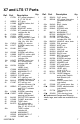
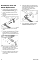


Table Of Contents
12 3A5572B EN
Pump Assembly
Replacement
To replace the pump assembly, first
disassemble the enclosure. See Front
Cover and Enclosure Replacement, page
8.
1. Remove suction hose and drain tube
from pump (1).
2. Loosen screw (22a) retaining the green
ground wire to the back of the drive (2)
and remove the ground wire.
3. Remove motor fan cover by gently
prying adjacent to its narrow retention
bars with a flat blade screwdriver. NOTE:
Prying on the bars themselves can
cause damage.
4. Remove 2 motor screws (T-20 Torx).
Pull motor (5) from the pump/drive
assembly. Be careful not to damage the
cooling fan.
5. Remove gear cover (18). Remove the
two screws (4) at the bottom of the
pump/drive assembly then remove the
pump/drive assembly.
6. Place the pump/drive assembly in a vise
with the jaws clamping on the flat sides at
the bottom of the pump (1).
7. Open the latch at the bottom of the
setting indicator (31), remove it from the
pressure control (8).
8. Remove the two screws (4) holding the
drive (2) to the pump (1), then rotate the
drive bracket approximately 90°.
9. Pull the drive assembly (2) and pump
piston from the pump (1). If necessary,
tap on the shorter leg of the drive with a
plastic hammer to separate the parts.
NOTE: Prying between the pump and
the drive can damage the drive and lead
to failure of equipment.
10. Verify that a small amount of grease has
been applied to the drive pocket in the
pump piston in the replacement pump
(1).
11. Rotate the drive gear to bring the stud
towards the pump, then insert the stud
into the piston pocket. Align the drive
shaft with the pump bushing, then push
the drive into the pump, rotating the gear
to draw the drive inward. Press the drive
and pump fully together. If necessary,
tap on the bottom of the drive with a
plastic hammer to seat the piston in the
pump.
12. Install two screws (4) at the top of the
drive (2). Torque to 80-90 in-lb (9.0-10.2
N•m).
13. Assemble motor (5) to the drive (2) with
the black wire lead on the pressure
control (8) side of the sprayer. Install 2
motor screws (T-20 Torx). Torque to
26-32 in-lb (2.9-3.6 N•m).
14. Route the motor leads through the ports
in the motor fan cover. Snap the cover
onto the motor (5).
15. Replace foam pad on motor bracket (6).
16. Place the pump/drive/motor assembly
on the motor bracket (6), then install the
two screws (4) at the bottom of the drive
(2). Torque to 80-90 in-lb (9.0-10.2 N•m).
17. Reassemble gear cover (18).
18. Route the pressure control wire harness
through the setting indicator (31). Install
the indicator around the pressure control
(8), snap together. Pass the wire
harness through the front cover (16),
aligning the indicator with the opening in
front cover as they are positioned loosely
on the pump.
19. Attach green ground wire to back of the
drive assembly (2) using screw (22a).
Torque to 25-35 in-lb (2.8-4.0 N•m).
20. Replace the suction and drain hoses on
the pump (1), and secure with their
clamps
21. Install front cover and enclosure. See
Front Cover and Enclosure
Replacement, page 8.
22. After assembly is complete, perform
Assembly Verification, page 13.