
Replacement Part List
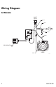
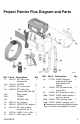
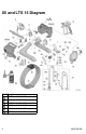
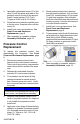
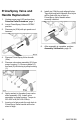
Table Of Contents

8 3A5572B EN
Front Cover and
Enclosure Replacement
Before servicing the sprayer, the enclosure
and front cover may need the removed.
Removal
1. Unplug power cord (22) and perform
Pressure Relief Procedure, page 1.
2. Remove front cover screws (16a) (T-30
Torx).
3. X7 and LTS 17 only: Remove underside
shroud screw (10d).
4. Remove enclosure screws (10b) (T-20
Torx), and remove right shroud (10).
5. If replacing the enclosure, disconnect all
wire leads and connectors from control
board (13) and ON/OFF switch. Remove
screw (13a) from control board bracket
to remove control board assembly (13)
from left shroud (10).
6. Remove left shroud (10) and front cover
(16).
Replacement
1. Install power cord (22) into recess on left
shroud (10).
2. Install control board assembly (13) to left
shroud (10) using screw (13a).
3. Reconnect all wire leads and connectors
to control board (13) and ON/OFF
switch. See Wiring Diagram, page 2.
4. Assemble front cover (16) and enclosure
(10).
5. Install enclosure screws (10b) (T-20
Torx). Torque to 20-25 in-lb (2.3-2.8
N•m).
6. X7 and LTS 17 only: Install underside
shroud screw (10d). Torque to 25 - 35
in-lb (2.8-4.0 N•m).
7. Install front cover screws (16a) (T-30
Torx). Torque to 36 - 42 in-lb (4.1-4.7
N•m).
8. Perform Assembly Verification, page
13.
Control Board
Replacement
To replace the control board, first
disassemble the enclosure. See Front
Cover and Enclosure Replacement, page
8.
1. Remove control board mounting screw
(13a) and control board (13) from left
side shroud (9).
2. If needed, assemble replacement
control board into bracket.
3. Install control board assembly (13) to left
side shroud (9) with mounting screw
(13a). Torque to 12-16 in-lb (1.4-1.8
N•m).
4. Install front cover and enclosure. See
Front Cover and Enclosure
Replacement, page 8.
5. After assembly is complete, perform
Assembly Verification, page 13.
Motor Replacement
To replace the motor, you must first
disassemble the enclosure. See Front
Cover and Enclosure Replacement, page
8.
1. Disconnect motor leads from control
board (13) and power cord (22).
2. Remove fan cover by gently prying
adjacent to its narrow retention bars with
a flat blade screwdriver. NOTE: Prying
on the bars themselves can cause
damage.
3. Remove 2 motor screws (T-20 Torx).
Pull motor (5) from the pump/drive
assembly. Be careful not to damage the
cooling fan.
NOTICE
Do not pinch wires between enclosure, front
cover, motor, and pump/drive assembly.