INSTRUCTIONS 309828N Important Safety Instructions Read all warnings and instructions in this manual. Save these instructions. G–Force Direct-Drive Pressure Washer 2525LD Model 246601, Series A & Series B 2300 psi (159 bar, 15.8 MPa) Maximum Operating Pressure 2500 psi (172 bar, 17.2 MPa) Maximum Working Pressure 2626LD Model 249065, Series A 2600 psi (179 bar, 17.9 MPa) Maximum Operating Pressure 2750 psi (191 bar, 19.0 MPa) Maximum Working Pressure 2525LD 2626LD ti6075a GRACO INC. ti3224b P.O.
Table of Contents Symbols . . . . . . . . . . . . . . . . . . . . . . . . . . . . . . . . . . . . . . 2 Warnings . . . . . . . . . . . . . . . . . . . . . . . . . . . . . . . . . . . . . . 3 Component Identification . . . . . . . . . . . . . . . . . . . . . . . . 4 Pressure Relief Procedure . . . . . . . . . . . . . . . . . . . . . . . 7 Installing and Changing Spray Tips . . . . . . . . . . . . . . 12 Pump Service . . . . . . . . . . . . . . . . . . . . . . . . . . . . . . . . . 19 Parts Drawing . . . . .
FUEL HAZARD: Fuel is combustible. When spilled on a hot surface it can ignite and cause a fire. Do not fill fuel tank while engine is running or hot. EXHAUST HAZARD: Exhaust contains poisonous carbon monoxide, which is colorless and odorless. Do not operate this equipment in a closed building. EQUIPMENT MISUSE HAZARD: Misuse of pressure washer or accessories can cause the equipment to rupture or malfunction and result in serious injury.
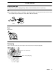
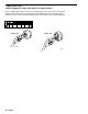
Component Identification Garden Hose Connection High Pressure Hose Connection Hose Rack (a) / Gun Holder (b) Tip Storage (b) Gun and Wand Water Pump Oil Fill Handle Release Button* On/Off Engine Switch (side) ti3226a Engine Oil Fill Thermal Valve *Cart handle can be removed to create a compact profile for storage and transporting. Push in release button on each side of handle. (Fig. 1) Pull handle off lower frame. (Fig. 2). Rotate handle 180 and reposition over lower frame. (Fig.
Initial Setup Shipping Damage Check pressure washer for shipping damage. Notify carrier immediately if there is any damage. Oil Engine is shipped without engine oil. Add Graco SAE 10W–30 engine oil (included) and confirm oil level is within an acceptable range according to the Honda Owner’s Manual (included). (cold) ti5952a Fuel Fill fuel tank. ti5953a Pump plug Remove red water pump plug (A) and replace with attached black vented pump plug (B).
Installation Connect High–Pressure Hose and Gun Connect high–pressure hose between the pump outlet and gun inlet. Both of these connections are made with quick couplers. ti3457a Note: Adapter kit 249101 can be used to connect two high pressure hoses together. ti7345a Install Spray Tip Install spray tip on wand. Installing and Changing Spray Tips, page 12). If you are using a Sandblasting Kit, see its separate manual for installation instructions.
PRESSURE RELIEF Follow these instructions whenever you are instructed to relieve pressure, stop spraying for more than 10 minutes, check or service the equipment, or install or clean the spray nozzle. 1. Engage trigger safety latch TI3233A 2. Turn pressure washer off 3. Remove ignition cable from spark plug. 4. Shut off water supply. Disconnect from water. 5. Disengage trigger safety latch. Trigger gun to relieve pressure. Then re–engage the safety latch.
Operation Startup Always use this startup procedure to ensure that the pressure washer is started safely and properly. Always engage gun trigger safety latch when you stop spraying. This reduces the risk of fluid injection or splashing in eyes or on skin if gun is bumped or accidentally triggered. Always observe the CAUTIONS in this section to avoid costly damage to pressure washer. If you use the Sandblaster Kit, see Sandblaster Kit Manual for detailed cleaning information. 1. . of engine.
4. Trigger gun until a constant stream of water sprays from tip indicating air is purged from the system. 5. Be sure spark plug ignition cable is pushed firmly onto spark plug. 6. For Model 2525LD ONLY, move throttle to Rabbit (fast) position first. All models Model 2525 Only For all models, (then) move choke to CHOKE position. ti3242a ti3240a 7. Pull the starter rope quickly to start the engine. Pull and return the rope until the engine starts.
Trigger Safety Latch Always engage the safety latch when you stop spraying. Always engage trigger safety latch when you stop spraying even for a moment. The engaged safety latch prevents the gun from being triggered accidentally by hand or when dropped or bumped. Be sure latch is pushed fully down or it will not prevent the gun from being triggered.
Chemical Injector Operation 1. Follow Pressure Relief Procedure, page 7. 2. Push end of chemical injector hose over chemical injector fitting on pump. Place other end in container of chemical solution. ti3237b 3. Install the black, large–orifice, chemical tip. (Installing and Changing Spray Tips page 12). 4. Trigger gun for a few seconds. Chemical solution will begin mixing in spray pattern. The large orifice of the chemical tip causes a drop in pressure that actuates the chemical injector.
Installing and Changing Spray Tips Spray tips have 4– or 5–digit numbers on them. The first two digits are the spray angle. Tip holding holes are provided on the chassis. Spray Pattern Fan Angle Spray Tip Number 00XXX 0 blaster (red) 15XXX 15 (yellow) 25XXX 25 (green) 40XXX 40 (white) Chemical XX (black) NOTE: The chemical injector tip is brass and has a large opening and a black plastic cap. 1. Perform Pressure Relief Procedure, page 7. 2.
Shutdown, Flushing, and Storage 1. Remove chemical injector hose from pump, if attached. 2. Trigger gun for one minute to flush pump with clear water. 3. Engage trigger safety. TI3233A 4. For model 2525LD, adjust throttle to STOP position. Engine should turn off. For model 2626LD, turn OFF power switch.
5. Shut off water supply. Disconnect water supply hose from pump. ti3231a 6. Remove trigger safety latch and trigger gun to relieve pressure. TI3234a 7. Remove high pressure hose from pump. Drain water from all components. ti3247b After each use, wipe all surfaces of pressure washer with a clean, damp cloth.
Long Term (more than 30 days)/Winter Storage Do not store unit outside where it can be exposed to rain, dirt or adverse weather conditions. Do not expose pressure washer to freezing temperatures or allow water to freeze in pressure washer components, causing the pump to lock–up. If this happens let pump thaw naturally in WARM ENVIRONMENT. DO NOT attempt to to speed up this process by pouring warm water on pump. This could cause further damage. ENGINE: 1.
Maintenance Chart Perform Pressure Relief Procedure (page 7). Interval What to do Daily Clean water inlet screen and filter. Check engine and pump oil levels. Fill as necessary. Check gasoline level. Fill as necessary. After first 5 hours of operation Change engine break-in oil. Drain oil when warm. Use SAE 30 or 10W–30 detergent oil. Every 3 months or 25 hours of operation Clean and remove air cleaner foam. Wash with water and detergent. Dry thoroughly. Rub with oil, and squeeze to distribute oil.
Troubleshooting Perform Pressure Relief Procedure (page 7). Problem Cause Engine will not start or No gasoline in fuel tank or carburetor is hard to start. Solution Fill tank with gasoline, open fuel shutoff valve. Check fuel line and carburetor. Low oil Add oil to proper level. Throttle in STOP position (model 2525LD only) Move throttle to FAST (rabbit) position Water in fuel or old fuel Drain fuel tank and carburetor. Use new fuel andmake sure spark plug is dry.
Problem Packings are failing freq entl or frequently prematurely Cause Solution Scored, damaged, or worn plungers Install new plungers. Abrasive material in fluid being pumped Install proper filtration on pump inlet plumbing. Inlet water temperature too high Check water temperature. It should not exceed 160 F (70 C). Overpressurizing pump Do not modify any factory–set adjustments. Excessive pressure due to partially plugged or damaged tip Clean or replace tip.
Pump Service Repair kits are available. See the Parts Lists (page 21). For the best results, use all parts in the kits. Perform Pressure Relief Procedure (page 7). Servicing Valves Discharge Valves: Disassembly 1. Remove valve cap. 2. Inspect valve cap o–ring for damage. Replace if necessary. 3. Using a needle nose pliers, remove valve. Inlet Valves Disassembly 1. Remove manifold. 2. Remove low–pressure seals by inserting a flat screwdriver under seal lip and lifting up. 3.
Packings Disassembly Assembly 1. To access water seals for inspection or replacement, remove head of pump. 1. Install high–pressure seal into head. Note: It is important to note the order in which the components of the packing stack are arranged and facing during disassembly. Note: It should fit snugly. The packing support is part of the valve cage. 2. Remove head bolts. 3.
Parts Model 2525LD 4 2 20 23 24 5 25 26 9 6 7 8 27 21 3 35 1 33 10 29 43,44 12 30 32 34 28 56 13 45 22 14 40 31 ti7343a 22 15 36 16 17 309828 21
Parts Model 2525LD Ref. Part No. No. Description Qty. Ref. Part No. No. Description Qty.
Repair Kits SJV2.5G25D–F7 (Use with model 2525LD) 1 2 57 3 4 5 6 7 6 8 5 9 55 48 10 11 12 13 14 15 16 17 18 19 30 31 26 27 32 28 44 62 43 40 21 23 47 46 41 45 49 63 66 24 33 25 34 35 ti6080c 36 37 38 SJV2.
Parts Model 2626LD 4 2 20 24 23 5 25 26 9 6 7 8 27 21 3 35 1 33 10 29 43,44 12 30 32 34 28 56 45 13 22 14 40 31 ti7344a 22 15 36 16 17 24 309828
Parts Model 2626LD Ref. Part No. No. Description Qty. Ref. Part No. No. Description Qty.
Repair Kits SJV2.5G27–D105 (Use with Model 2626LD) 1 2 3 4 5 6 7 6 8 55 5 9 48 10 30 31 11 12 14 16 18 26 13 27 15 28 47 46 32 44 43 17 19 40 21 23 41 62 49 63 45 24 25 33 34 66 35 ti6163b 36 37 38 SJV2.
Technical Data Model 2525LD Working pressure range Operating Pressure 2300 psi (159 bar, 15.8 MPa) Maximum Working Pressure 2500 psi (172 bar, 17.2 MPa) Engine horsepower 5.0 Maximum delivery (with nozzle) 2.5 gpm High pressure hose 30 ft x 5/16 in. supplied Chemical injector hose 4 ft ( m) 1/4 in. ID Weight, pressure washer only 60 lb (27.22 kg) Weight: sprayer, hose and gun 73 lb (33.11 kg) Dimensions 23.5 in. (59.69 cm) Length 22.0 in. (55.88 cm) Width 22.0 (55.
Graco Standard Warranty Graco warrants all equipment listed in this manual which is manufactured by Graco and bearing its name to be free from defects in material and workmanship on the date of sale to the original purchaser for use. Graco will, for a period of twelve months from the date of sale, repair or replace any part of the equipment determined by Graco to be defective.