
User's Manual


Service
6. Remove
the valve seat (1) and the gasket (9) from the
housing (25).
7.
Clean all the parts with a compatible solvent. Check the
parts for wear or damage. Replace worn or damaged
parts.
8.
Assemble the valve seat (1) and the gasket (9) into the
housing (25). T
orque to 70–80 in–lb (8–9 N.m).
9.
Assemble the diaphragm and the related parts as shown
in the parts drawing. T
orque the cap nut (4) to 27–33
in–lb (3.1–3.7).
10.
Install the spring (13) and the spring plate (15).
11.
Screw the cap (28) onto the housing (25). T
orque to
1
15–125 in–lb (13–14 N.m). Reinstall the locknut (27)
and the adjusting screw (26) into the cap (28).
12.
Assemble the inlet adapter (22) and the outlet union (1
1)
into the housing.
13.
Assemble the gauge (5) to the pressure tube (16). Use a
thread sealant to ensure a good seal. Install the tube and
the gauge into the inlet adapter (22).
14.
Install the valve in the system.
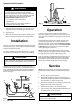
Parts
04519
26
27
28
15
13
4
10
18
20
21
19
2
1
9
11
25
5
16
22
7
Torque
to
1
15–125 in–lb
(13–14 N.m)
T
orque to
27–33 in–lb
(3.1–3.7 N.m)
T
orque to
70–80 in–lb
(8–9 N.m)
Ref.
No. Part No. Description Qty.
1 236–893 SEAT, valve 1
2 236–894 STEM, valve 1
4 100–529 NUT
, hex, cap, 5/16–18
1
5 187–876 PRESSURE GAUGE, 0–300 psi
(0–21 bar
, 0–2.1 MPa) pressure range
1
7 101–976 WRENCH, hex key
, 3/8”
1
9 189–817 GASKET
, copper
1
10 154–789 GASKET
, copper
1
11 155–665 UNION, 3/8 npt(m) x
3/8 npsm(f) swivel 1
13 157–796 SPRING, compression 1
15 160–180 PLA
TE, spring
1
16 160–745
TUBE, fluid gauge
1
18 189–816 PLATE, backup 1
19 177–430 GASKET, valve 1
20 177–432 DIAPHRAGM PLA
TE, support
1
21 177–431 DIAPHRAGM 1
22 162–265
INLET ADAPTER, 3/8–18 npsm(m),
3/8–18 npt(m), 1/4–18 npt(f)
1
25 162–811 VALVE HOUSING 1
26 112–844 ADJUSTING SCREW
, 1/2–20 x
1–5/8 inch long
1
27 100–111 LOCKNUT
, 1/2–20
1
28 189–815 REGULATOR CAP 1
Keep these spare parts on hand to reduce down time.
Graco
Phone
Number
TO PLACE AN ORDER
, contact your Graco distributor
, or
call this number to identify the distributor closest to you:
1–800–367–4023 T
oll Free
Manual
Change
Summary
Assembly
Changed
Part
Status
Ref
No.
Part
No.
Name
205–122
Series to C
Old
New
Old
New
1
1
5
5
212–030
236–893
101–180
187–876
Seat
Seat
Gauge
Gauge
Maximum inbound fluid pressure is increased to 300 psi (21
bar
, 2.1 MPa).