INSTRUCTIONS-PARTS LIST This manual contains important warnings and information. READ AND KEEP FOR REFERENCE. 307–159 Rev. K Supersedes Rev. J INSTRUCTIONS Viscount II 4500 Pump 1500 psi (100 bar, 10 MPa) Maximum Hydraulic Input Pressure 4500 psi (310 bar, 31 MPa) Maximum Working Pressure Model 221–066, Series B With Severe-Duty Displacement Pump* and Quiet Hydraulic Motor * Severe-Duty displacement pumps have an abrasion and corrosion-resistant displacement rod and cylinder.
Table of Contents Warnings . . . . . . . . . . . . . . . . . . . . . . . . . . . . . . . . . . . . . . 2 Installation . . . . . . . . . . . . . . . . . . . . . . . . . . . . . . . . . . . . 5 Operation . . . . . . . . . . . . . . . . . . . . . . . . . . . . . . . . . . . . . 8 Maintenance . . . . . . . . . . . . . . . . . . . . . . . . . . . . . . . . . . 10 Troubleshooting . . . . . . . . . . . . . . . . . . . . . . . . . . . . . . . 11 Service . . . . . . . . . . . . . . . . . . . . . . . . . . . . . . .
WARNING INJECTION HAZARD Spray from the gun/valve, leaks or ruptured components can inject fluid into your body and cause extremely serious injury, including the need for amputation. Fluid splashed in the eyes or on the skin can also cause serious injury. Fluid injected into the skin might look like just a cut, but it is a serious injury. Get immediate medical attention. Do not point the gun/valve at anyone or at any part of the body. Do not put your hand or fingers over the spray tip/valve nozzle.
WARNING FIRE AND EXPLOSION HAZARD Improper grounding, poor ventilation, open flames or sparks can cause a hazardous condition and result in a fire or explosion and serious injury. Ground the equipment and the object being sprayed. Refer to Grounding on page 5. If there is any static sparking or you feel an electric shock while using this equipment, stop spraying/dispensing immediately. Do not use the equipment until you identify and correct the problem.
Installation General Information 4. Spray gun: ground through connection to a properly grounded fluid hose and sprayer. NOTE: Reference numbers and letters in parentheses in the text refer to the callouts in the figures and the parts drawing. 5. Object being sprayed: follow your local code. NOTE: Always use Genuine Graco Parts and Accessories, available from your Graco distributor. Grounding WARNING FIRE AND EXPLOSION HAZARD Before operating the pump, ground the system as explained below.
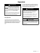
Installation E F H J N K C L S G D A R P B T Q M 06639 Key A B C D E F G H J Fluid Hose to Gun Fluid Drain Valve Suction Hose Hydraulic Return Line Hydraulic Return Line Shutoff Valve Pressure Gauge Flow Control Valve Pressure Reducing Valve Accumulator K L M N P Q R S T Drain Line (from pressure reducing valve) Hydraulic Supply Line Hydraulic Power Supply Ground Wire Wet-Cup Drain Line (from motor drip pan) Check Valve Hydraulic Supply Line Shutoff Valve Return Line Filter Fig.
Installation Hydraulic Lines Operating Temperature The motor has a 3/4 npt(f) hydraulic oil supply fitting, and a 1” npt(f) hydraulic oil return fitting. Usa a minimum 1/2 in. ID hydraulic supply line and a minimum 7/8 in. ID, return line. Keep the hydraulic oil temperature below 130_ F (54_ C) for maximum pump performance. On the hydraulic supply side (C), install the following accessories shown in Fig. 2, using adapters as necessary.
Operation Pressure Relief Procedure WARNING INJECTION HAZARD Fluid under high pressure can be injected through the skin and cause serious injury. To reduce the risk of an injury from injection, splashing fluid, or moving parts, follow the Pressure Relief Procedure whenever you: are instructed to relieve the pressure, stop spraying/dispensing, check or service any of the system equipment, or install or clean the spray tips/nozzles. 1.
Operation WARNING COMPONENT RUPTURE HAZARD To reduce the risk of overpressurizing your system, which could cause component rupture and serious injury, never exceed the specified Maximum Incoming Air Pressure to the pump (see the Technical Data on page 15). To prevent overpressurizing the hydraulic motor or its seals, always shut off the supply line valve (S) first, then shut off the return line valve (E). Pump Operation To operate the pump, turn on the hydraulic power supply.
Maintenance WARNING To reduce the risk of serious injury whenever you are instructed to relieve pressure, always follow the Pressure Relief Procedure on page 8. Keep the wet-cup (P) 1/3 filled with Graco Throat Seal Liquid (TSL) Check the tightness of the packing nut weekly. Before adjusting, relieve the pressure. The packing nut should be tight enough to stop leakage, but no tighter. Overtightening will compress and damage the packings and result in pump leaking.
Troubleshooting WARNING To reduce the risk of serious injury whenever you are instructed to relieve pressure, always follow the Pressure Relief Procedure on page 8. Before servicing this equipment, always make sure to relieve the pressure. NOTE: Check all possible problems and solutions before disassembling the pump. Problem Cause Solution Pump operates, but output low on both strokes Restricted lines or inadequate hydraulic supply Clear lines; increase hydraulic supply.
Service Disconnecting the Hydraulic Motor WARNING To reduce the risk of serious injury whenever you are instructed to relieve pressure, always follow the Pressure Relief Procedure on page 8. Remove the tie rod lock nuts (3), then unscrew the tie rods (6) from the hydraulic motor base. See the parts drawing on page 13. See separate instruction manual 307–158 for hydraulic motor service instructions, and 307–728 for the displacement pump. Relieve the pressure.
Parts 1 Torque to 40–50 ft-lb (54–68 NSm) 34 Ref. No. Part No. Description 1 100–103 3 4 5 6 7 8 9 11 101–712 101–936 158–674 167–911 168–210 168–211 168–212 217–527 34 221–168 35 36 158–586 203–916 37 38* 39 40 41 42 203–921 101–454 151–220 160–494 160–516 162–289 PIN, cotter; 0.125” (3.18 mm) x 1.50” (38.
Dimensions Mounting Hole Layout Gasket 161–806 1” npt(f) Outlet 3/4 npt(f) Inlet 45.8” (1163 mm) 4” (102 mm) Four .437” (11.1 mm) holes on 10.5” (267 mm) bolt circle 9.75” (247.7 mm) 1.38” (34.9 mm) R 90 45 06595 1” npt(f) 20.9” (531 mm) 1–1/2” npt(f) 06638 Accessories HYDRAULIC FLUID, Graco-Approved 207–428 1 gallon (3.8 liter) 169–236 5 gallons (19 liters) 14 307-159 POLYETHYLENE TUBE 054–106 0.25 in. (6.4 mm) ID; 0.375 in. (9.5 mm) OD.
Technical Data Maximum hydraulic input pressure . . . . . . . . . . . . . . . . . . . . . . . . . . . . . . . . . . . . . . . . . . . . 1500 psi (100 bar, 10.0 MPa) Maximum pump output pressure . . . . . . . . . . . . . . . . . . . . . . . . . . . . . . . . . . . . . . . . . . . . . . 4500 psi (310 bar, 31.0 MPa) Maximum recommended pump speed . . . . . . . . . . . . . . . . . . . . . . . . . . 50 cycles per minute – 3.3 gpm (12.5 liter/min) Hydraulic fluid consumption . . . . . . . . . . . . . . . . . . .
The Graco Warranty and Disclaimers WARRANTY Graco warrants all equipment listed in this manual which is manufactured by Graco and bearing its name to be free from defects in material and workmanship on the date of sale by an authorized Graco distributor to the original purchaser for use. Graco will, for a period of twelve months from the date of sale, repair or replace any part of the equipment determined by Graco to be defective.