Instructions -- Parts List ViscountR II Pump Hydraulic powered, severe duty pump for use with solventborne and waterborne paints and coatings. 1500 psi (10.3 MPa, 103 bar) Maximum Hydraulic Input Pressure 1000 psi (7 MPa, 69 bar) Maximum Pump Outlet Pressure Model 210313, Series E With Severe-Duty Displacement Pump* * Severe-Duty displacement pumps have an abrasion and corrosion-resistant displacement rod and cylinder.
Table of Contents Warnings . . . . . . . . . . . . . . . . . . . . . . . . . . . . . . . . . . . . . . 2 Installation . . . . . . . . . . . . . . . . . . . . . . . . . . . . . . . . . . . . . 5 Operation . . . . . . . . . . . . . . . . . . . . . . . . . . . . . . . . . . . . . 8 Maintenance . . . . . . . . . . . . . . . . . . . . . . . . . . . . . . . . . . 10 Troubleshooting . . . . . . . . . . . . . . . . . . . . . . . . . . . . . . . 11 Service . . . . . . . . . . . . . . . . . . . . . . . . . . . . . .
WARNING INJECTION HAZARD Spray from the gun/valve, leaks or ruptured components can inject fluid into your body and cause extremely serious injury, including the need for amputation. Fluid splashed in the eyes or on the skin can also cause serious injury. D Fluid injected into the skin might look like just a cut, but it is a serious injury. Get immediate medical attention. D Do not point the gun/valve at anyone or at any part of the body. D Do not put your hand or fingers over the spray tip/valve nozzle.
WARNING FIRE AND EXPLOSION HAZARD Improper grounding, poor ventilation, open flames or sparks can cause a hazardous condition and result in a fire or explosion and serious injury. D Ground the equipment and the object being sprayed. Refer to Grounding on page 5. D If there is any static sparking or you feel an electric shock while using this equipment, stop spraying/dispensing immediately. Do not use the equipment until you identify and correct the problem.
Installation General Information NOTE: Reference numbers and letters in parentheses in the text refer to the callouts in the figures and the parts drawing. NOTE: Always use Genuine Graco Parts and Accessories, available from your Graco distributor. Grounding WARNING FIRE AND EXPLOSION HAZARD Before operating the pump, ground the system as explained below. Also read the section FIRE OR EXPLOSION HAZARD on page 4. D Spray gun: Ground through connection to a properly grounded fluid hose and sprayer.
Installation Mount the pump to suit the type of installation planned. Pump dimensions and mounting hole layout are shown on page 14. CAUTION The hydraulic supply system must be kept clean at all times to avoid damage to the motor and hydraulic power supply. Blow out all hydraulic lines with air and flush thoroughly with compatible solvent before connecting the lines to the motor.
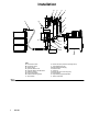
Installation E F H J K C N L S D G P A R T B Q 0627A M KEY A Fluid Hose to Gun B Fluid Drain Valve C Suction Hose D Hydraulic Return Line E Hydraulic Return Shutoff Valve F Pressure Gauge G Flow Control Valve H Pressure Reducing Valve J Accumulator Fig.
Operation Pressure Relief Procedure WARNING INJECTION HAZARD Fluid under high pressure can be injected through the skin and cause serious injury.
Operation WARNING COMPONENT RUPTURE HAZARD To reduce the risk of overpressurizing your system, which could cause component rupture and serious injury, never exceed the specified Maximum Hydraulic Input Pressure to the pump (see the Technical Data on page 15). To prevent overpressurizing the hydraulic motor or its seals, always shut off the supply line valve (S) first, then shut off the return line valve (E).
Maintenance Carefully monitor your fluid supply. If your pump us running too fast, or accelerates quickly, it is probably out of fluid. Shut off the hydraulic power supply immediately to prevent damage to the pump. If the fluid supply is empty, and air has entered the fluid lines, be sure to prime the pump again before regular operation. Flush the pump frequently enough to prevent the fluid from drying or settling in the pump and hoses to prevent costly damage. Use a compatible solvent.
Troubleshooting WARNING To reduce the risk of serious injury whenever you are instructed to relieve pressure, always follow the Pressure Relief Procedure on page 8. Before servicing this equipment, always make sure to relieve the pressure. NOTE: Check all possible problems and solutions before disassembling the pump. Problem Cause Pump fails to operate Restricted lines or inadequate hydraulic Clear lines. Increase hydraulic supply.
Service NOTE: To service the displacement pump, refer to manual 308043, supplied. NOTE: To service the hydraulic motor, refer to manual 308158, supplied. 1 Torque to 40--50 ft-lb (54--68 NSm) Disassembly (See Fig. 6) WARNING To reduce the risk of serious injury whenever you are instructed to relieve pressure, always follow the Pressure Relief Procedure on page 8. 11 1. Flush the pump with a compatible solvent, if possible. Stop the pump at the bottom of its stroke. Relieve the pressure. 2.
Parts 11 8 7 5 1 9 6 4 1 12 3 06640 13 307160 Ref. No. Part No. Description 1 3 100103 101712 4 5 6 101936 158674 167911 7 8 9 168210 168211 168212 11 235345 12 210208 PIN, cotter; 1.5” (38.1 mm) long LOCKNUT; 5/8--11; with nylon insert NUT, hex, jam; 3/4--10 O-RING; nitrile rubber ROD, tie; 7” (177.8 mm) long, shoulder-to-shoulder NUT, shouldered COUPLING, connecting rod ROD, connecting; 3.69” (93.
Dimensions Mounting Hole Layout gasket 161806 1” npt outlet 3/4 npt inlet 48.1” (1220 mm) 4” (102 mm) four 0.437” (11.1 mm) holes on 10.5” (267 mm) bolt circle 9.75” (247.7 mm) diameter 90_ 23.2” (585 mm) 45_ 1--1/2” npt fluid outlet 06641 2” npt fluid inlet 14 307160 1.38” (34.
Technical Data Maximum hydraulic input pressure . . . . . . . . . . . . . . . . . . . . . . . . . . . . . . . . . . . . . . . . . . . . 1500 psi (10.3 MPa, 103 bar) Maximum pump outlet pressure . . . . . . . . . . . . . . . . . . . . . . . . . . . . . . . . . . . . . . . . . . . . . . . . . 1000 psi (7.0 MPa, 69 bar) Hydraulic fluid consumption . . . . . . . . . . . . . . . . . . . . . . . . . . . . . . . . . . . . . . . . . . . . . . . . . . . . 0.2 gal (0.
Graco Standard Warranty Graco warrants all equipment manufactured by Graco and bearing its name to be free from defects in material and workmanship on the date of sale by an authorized Graco distributor to the original purchaser for use. With the exception of any special, extended, or limited warranty published by Graco, Graco will, for a period of twelve months from the date of sale, repair or replace any part of the equipment determined by Graco to be defective.