INSTRUCTIONS-PARTS LIST OJ OIlACO 307-896 Rev. A This manual contains IMPORTANT WARNINGS and INSTRUCTIONS READ AND RETAIN FOR REFERENCE AUTOMATIC HIGH-RANGE ELECTROSTATIC AIR SPRAY GUN 7 bar (100 psi) MAXIMUM WORKING PRESSURE Part Number 907-292 Spray Gun & 75 ft. High Voltage Cable Part Number 956-112 Spray Gun & 50 Ft. High Voltage Cable Part Number 956-610 Spray Gun with 25 Ft. High Voltage Cable u.s. PATENT NO. 4,241,880; 4,335,861; and 4,501,394 H003 GRACO INC. P.O.
TABLE OF CONTENTS WARNINGS ...................................................................... 2 HOW THE ELECTROSTATIC AIR SPRAY GUN WORKS .......... 4 INSTALLATION Typlc.1 In.t.lI.tlon ......................................................... 4 V.ntll.te the Spr.y Booth ................................................ 4 Conn.ct the High Voltage Power Supply ........................... 4 Connect the High Volt.ge Ca........................................... 15 Ch.ck the Electrical Grounding .............
Bleed·Type AIr Shutoff Valve and fluid Drain Valve Required These two accessories are required in your system to help reduce the risk of serious bodily injury, including splashing in the eyes and injury from moving parts if you are adjusting or repairing the pump. The bleed-type air shutoff valve relieves air trapped between this valve and the pump after the air regulator is shut off.
How the Electrostatic Air Spray Gun Works A transformer supplies high voltage current through the cable to the gun's ionizing electrode, where the electrostatic field is developed. The pump supplies fluid through the hose and gun, where it is electrostatically charged as it passes the ionizing electrode. The charged fluid is attracted to the grounded workpiece, wrapping around it and coating all surfaces.
Connect the High Voltage Power Supply The electrical connections to the Power Supply (H) must be performed by a qualified electrician, in accordance with all applicable local, state and national codes. z--~=- Connect the High Voltage Cable Grease the resistor tube as described in Resistor Tube Regreasing on page 13. Route the High Voltage Cable (M) from the gun to the Power Supply. Lubricate o-rings with petroleum jelly. Connect the High Voltage Cable to the Power Supply.
Connect the High Voltage Control An electrical signal is required to actuate the normally closed, 3-way air solenoid valve (P). The air solenoid valve opens the cylinder air to the actuator, which opens the fluid needle, allowing the fluid to spray. The same signal (W) that actuates the air solenoid valve actuates a relay (T). A set of contacts from this relay is connected to the 120 KV Power Supply. This allows the High Voltage to be turned on and off automatically.
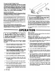
KEY 39 fi1 Fluid Adjusting Screw Fan Valve Assembly 39 Clean the Air Cap and Fluid Tip Equipment needed: Soft bristle brush (supplied). Fluid tip wrench (supplied). Solvent compatible with fluid being sprayed. Procedure: 1. Turn off the Power Supply. 2. Shut off the fluid and air supply lines to the gun. 3. Actuate the gun to release the air and fluid pressure trapped in the lines. 4. Note the position of the fluid adjusting screw (39). See Fig 4.
SERVICE ~----------------------------VVARNING----------------------------~ Installing and servicing this equipment requires access to parts which may cause electric shock or other serious bodily injury. Do not install or service this equipment unless you are qualified. Before servicing the tip or gun, and before disassembling the gun, ALWAYS follow the Pressure Relief Procedure on page 2. Disconnect the fluid hose from the gun.
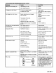
GUN OPERATION TROUBLESHOOTING CHART PROBLEM CAUSE SOLUTION Leakage from fluid packing nut. Loose packing nut (23). Tighten. Worn needle packing (4). Replace. Air valve not seating properly. Clean, service. Air bleed valve is open. Check, adjust or close as required. See Fig 2. Resistor electrode worn or damaged. Replace. Worn fluid seat. Replace fluid tip and/or resistor electrode. Fluid packing (4) too tight. Lubricate and adjust. Loose fluid tip (30). Tighten.
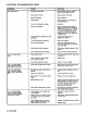
ELECTRICAL TROUBLESHOOTING CHART PROBLEM CAUSE SOLUTION Poor wrap-around. Parts poorly grounded. Clean hangers, check for proper ground on conveyer or track. High exhaust velocity. Reduce within code limits. High fluid pressure. Reduce pressure. Fluid viscosity. Check supplier for proper fluid for electrostatic spray. Low or no electrostatic voltage. See below. Faulty gun resistance.
ELECTRICAL TROUBLESHOOTING CHART PROBLEM CAUSE SOLUTION Low or no electrostatic wrap. (Spraying voltage light is on all of the time). Continued from page 10. Spring at transformer end of cable not making good contact. Stretch spring. Electrical short in gun. Take gun apart and visually check the resistor holder, the resistor well and needle well for dirt and/or damage. Clean and replace parts required. Faulty High Voltage Power Supply. See instruction manual included with High Voltage Power Supply.
Fluid Needle Removal (See Figs 7 and 8) Remove the air cap and fluid tip as described in the Operation Section under Clean the Air Cap and Fluid Tip. Turn the cylinder air off. Remove the electrode resistor (55). Note the position of the adjusting screw (39), and remove adjusting screw, retaining nut (35), spring (63) and washer (68). Remove plate (37), by removing the four screws (12). Loosen the needle packing nut (23) half a turn, using the wrench (83c) supplied.
KEY 4 Packing 20 SupPOrt 66 67 n 23 Packing Nut 28 29 44 Barrel Nut Support Insulator 60 Gun earrel O-Ring O-Ring Fitting 28~~\ ~~~ 20~ 6I~ 29 , ~,~ ~ c:/'/ i»®1' ~ ~66 ~n Fig 11 _ _ _ _ _ _ _ _ _ _ _ _ _ _ _ __ Check all of the parts for wear or damage and replace them if necessary. ...------CAUTION - - - - - - - . Use extreme care when handling the packing (4) because it is very brittle. You may want to keep extra pac kings on hand.
Replace the barrel as described in Barrel Reas.embly. Reassemble the electrode resistor (55), fluid tip (30), and air cap (32) as described in Clean the Air Cap and Fluid Tip in the Operation Section. Remove the housing (38), and spring (17) from the housing (65). Remove housing (65). Piston parts from the gun body (56) will come out with the housing. Clean all parts with compatible solvent and replace if worn.
AIR CAP CONSUMPTION AND FLUID TIP FLOW RATE CHART _ _ _Dm_ _WMmmlHS1i~gt*i]rn1Jm1~n:;;;%bWiitHfWJ NOTE: This is only a guide for selecting an air cap and fluid tip combination for your application. ALL TIPS AND CAPS ARE INTERCHANGEABLE. Contact your Graco representative for further information. RECOMMENDED AIR CAP AND FLUID TIP COMBINATIONS TYPE OF FLUID AND VISCOSITY Low Production Stains Primers Sealers lacquers 15 to 22 seconds (No.
0) <0 Q) ...... I 1 1 67 72 60 1 4 66 1 1 1 2 2 1 1 1 3 2 Qty. 29 58 24 6 7 8 10 14 16 20 Ref No. 4 Repair Kit 218-988 Must be ordered separately. ~ Consists of: a; 72* 83e r..... Tool Kit 216-642 (Ref No. 83; Includes 83a-83f) 53 .';' I ~I II; }.; ~ f,::::.; ~,·~ tm. t: . , I ~~· II l~ .>;• • . . x .:~.~ G) Z ~ ~ :u c :u ....
REF NO. 4 6 7 8 9 10 11 12 13 14 15 16 17 18 20 22 23 24 27 28 29 30 PART NO.
...------WARNING------, Never operate your equipment at a working pressure rating that is higher than the lowest rated component in your system. Lower rated components may not be able to withstand the pressure developed by the pump and may rupture, causing serious bodily injury or property damage. HIGH VOLTAGE POWER SUPPLY 956-155 115 VAC, 50/60 Hz. Contact your Graco distributor for information.
ACCESSO AI ES (Must be purchased separately) nmMmtW*iimim::ti/@Mm:N?HM1mtJM:Wt:tiIrl:i::fil:·::• ·:~: @Wi.{<:\·/?::)i· The accesaori.. on this page have not been tested by Factory Mutual. STRAINER (AIR or PAINT) 202-271 52 bar (750 psi) MAXIMUM WORKING PRESSURE With 60 mesh filter element. ~~ See instruction manual 306-655. ~ '-.. 3/8npt~ ~~~:: OUTLET 3/8 npt INLET FILTER-REGULATOR ASSEMBLY 217-07& 14 bar (200 psi) MAXIMUM WORKING PRESSURE With 1/2 npt(f) inlet, 1/4 npt(m) regulated outlets.
I -n cm ---33~~·5in.) ,I t--I: . .·-------------(13 I n . ' - - - - - - - - - - - - - I 17 cm (6.7 in.' 1/4 NPT AIR INLETS 12.5 em SIDE~ in.1 121 OPPOSITE 16 44 em 1--------------------(17.3 in.' TECHNICAL DATA Operating voltage range Maximum air working pressure Maximum fluid working pressure Minimum air cylinder operating pressure Fluid inlet Atomizing air inlet Cylinder air inlet Weight (with 50-foot cable) (gun only) Paint resistivity range 0-120 KV 10.4 bar (150 psi) 7 bar (100 psi) 3.