
User's Manual


22 308148
Service
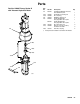
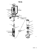
Reassembly
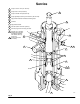
1. If it was necessary to remove the ball guide (9)
from the displacement rod (1), place the flats of
the rod in a vise. Apply anti-seize lubricant 222955
to the threads and mating faces of the rod and the
ball guide. Screw the ball guide onto the rod, hand
tight. Remove from the vise. See Fig. 8.
2. Place the female gland (13*) on the piston seat
housing (12). Install the five v-packings (P) one at
a time with the lips facing up. Refer to pages 30
and 32 for the correct packing order for your
pump. Install the male gland (11*).
NOTE: To convert the pump to a different packing
material, see pages 30 and 32.
NOTE: Service Tool 109507 is available as an acces-
sory. The tool fits over the top of the displacement rod
(1), making it easier to apply a 24 inch adjustable
wrench or 3/4 in. drive socket when connecting the rod
to the piston assembly.
3. Apply anti-seize lubricant 222955 to the threads
and mating faces of the ball guide (9) and piston
seat housing (12). Place the flats of the piston seat
housing in a vise. Place the ball (10) on the piston
seat. Screw the assembled rod (1) and ball guide
(9) onto the piston assembly hand tight, then
torque to 459–481 N.m (338–354 ft–lb).
4. Use an arbor press to reinstall the rod (1) into the
cylinder (7), as follows. (The cylinder is symmetri-
cal, so either end may face up.) Lubricate the
piston packings (P). With the piston end facing
down, lower the rod into the cylinder. Start the
piston into the cylinder as much as possible, then
drive the rod and piston the rest of the way into the
cylinder with the arbor press.
CAUTION
To reduce the possibility of costly damage to the rod
(1) and cylinder (7), always use an arbor press to
drive the rod into the cylinder, and be sure to place
the cylinder on a soft block of wood. Never use a
hammer to drive the rod.
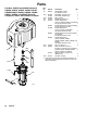
5. Lubricate the o-ring (27*) and seal (6*). Install the
o-ring on the intake seat housing (15). Install the
intake seat housing (15), intake ball (16), ball guide
(14), and seal (6*) in the intake housing (17). Set
the intake housing all the way into the vise.
6. Place the cylinder (7) on the intake housing (17).
Tap on the top of the displacement rod (1) with a
rubber mallet, to seat the cylinder.
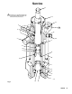
7. Lubricate the throat packings (T). Place the male
gland (29*) into the outlet housing (19). Install the
five v-packings one at a time with the lips facing
down. Refer to pages 30 and 32 for the correct
packing order for your pump. Install the female
gland (25*).
NOTE: To convert the pump to a different packing
material, see pages 30 and 32.
8. Lubricate the threads of the packing nut (3), and
loosely install it in the outlet housing (19).
9. Lubricate the seal (6*) and install it in the bottom of
the outlet housing (19). Set the outlet housing on
top of the cylinder (7). Apply thread lubricant to the
six long cap screws (20). Install the washers (33, if
present) and cap screws through the outlet hous-
ing (19) and thread them loosely by hand into the
intake housing (17). Tighten the cap screws oppo-
sitely and evenly, using a socket wrench, then
torque to 244–264 N.m (180–195 ft–lb).
10. Screw the housing valve (34) into the valve hous-
ing. Torque to 30–28 N.m (22–28 ft-lb).
NOTE: It is not ordinarily necessary to remove the
outlet fitting (4) and o-ring (5*). However, if they were
replaced because of damage, lubricate the o-ring and
place it on the fitting. Screw the fitting into the outlet
housing (19). Torque to 156–171 N.m (115–126 ft–lb).
11. Reconnect the displacement pump to the air motor
as explained on page 18.