
User's Manual

30822412
Installation
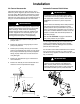
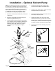
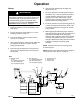
NOTE: If you mount the pump on a wall, turn the
displacement pump inlet assemblies (CC) to face
forward, rather than backwards as shown in Fig. 6.
Connect Fluid Supply Hoses
For Two Displacement Pump Models
1. Connect the resin supply hose (EE) to the 3/4 npt
swivel inlet (37B) for the resin displacement pump.
See Fig. 6.
2. Connect the hardener supply hose (DD) to the
3/4 npt swivel inlet (37A) for the hardener displace-
ment pump. See Fig. 6.
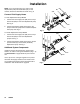
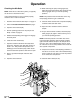
For Three Displacement Pump Models
1. Connect the resin supply hose (EE) to the 3/4 npt
swivel inlet (37B) for the resin displacement
pumps. See Fig. 7.
2. Connect the hardener supply hose (DD) to the 3/4
npt swivel inlet (37) for the center (hardener)
displacement pump. See Fig. 7.
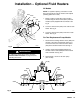
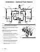
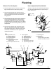
Additional System Components
Install and connect the feed pumps, solvent pump,
heaters, etc. Refer to the Typical Installation (Fig. 1–2)
and Accessories on pages 38–39 for parts informa-
tion.
Use a dry air kit or a nitrogen regulator kit to protect
the fluid in the supply containers from moisture that
can crystallize the fluid and cause the ball checks to
malfunction. See Accessories on page 39.
Fig. 6
DD
EE
CC
RES
HARD
02889
37B
37A
Fig. 7
DD
EE
HARD
37B
37A
02890
RES
RES