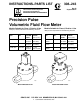
INSTRUCTIONS–PARTS LIST 308–243 Rev. B Supersedes A This manual contains important warnings and information. READ AND RETAIN FOR REFERENCE Precision Pulse Volumetric Fluid Flow Meter Models Suitable for Class , Division 2 Use Models Suitable for Class , Division 1 Use 2000 psi (140 bar) Maximum Fluid Working Pressure 3000 psi (210 bar) Maximum Fluid Working Pressure MODEL NO. PART NO. FLUID FLOW VOLUME RANGE gal/min (cc/min) FLOW MODEL NO. PART NO.
WARNINGS Serious injury, explosion, fire or electric shock can occur if the precautions below are not followed. Read and understand all instruction manuals, tags, and warning labels before operating equipment. Electrical equipment shall only be installed, operated, and serviced by trained, qualified personnel who shall be fully conversant with the requirements stated within this instruction manual.
Table of Contents Warnings . . . . . . . . . . . . . . . . . . . . . . . . . . . . . . . . . . . . . 2 Model PPM 3100H . . . . . . . . . . . . . . . . . . . . . . . . . 16 Installation . . . . . . . . . . . . . . . . . . . . . . . . . . . . . . . . . . . 4 Model PPM 3550H . . . . . . . . . . . . . . . . . . . . . . . . . 17 Operation . . . . . . . . . . . . . . . . . . . . . . . . . . . . . . . . . . . . . 8 Accessories . . . . . . . . . . . . . . . . . . . . . . . . . . . . . . . . . 18 Maintenance .
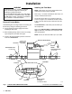
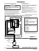
Installation WARNING Installing the Flow Meter To reduce the risk of fire, explosion, or electric shock, all electrical equipment must only be installed by a qualified electrician. Never install Models PPM 3050, 3100, and 3550 in a Class I, Division 1 hazardous location. Only Models PPM 3050H, 3100H, and 3550H are suitable for Class I, Division 1 hazardous location. NOTE: Flow volume can only be measured at the location where the flow meter is installed. Refer to Fig.
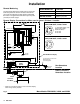
Installation Check the Electrical Grounding WARNING Remote Monitoring The flow meters are designed for use with the Graco PPD 200 Remote Displays. See Accessories for part numbers and descriptions. Proper electrical grounding of your system is essential. For your safety, read the warning section, FIRE, EXPLOSION, OR ELECTRIC SHOCK HAZARD, on page 2. See Fig. 2 to connect the remote display to meter models PPM 3050, 3100, and 3550. See Fig.
Installation Remote Monitoring The flow meter will send an output pulse for each gear tooth that passes the sensor. The actual K-factor for your meter is marked on the data sheet included with the meter. The approximate flow volume per one pulse (K-factor) is shown at right. METER MODEL NO. K-FACTOR PPM 3050 & 3050H 0.1136 cc per pulse PPM 3100 & 3100H 0.2294 cc per pulse PPM 3550 & 3550H 0.
Installation Remote Monitoring When Meter is in a Class , Division 1 Hazardous Location Models PPM 3050H, 3100H, and 3550H ONLY WARNING To reduce the risk of fire and explosion and serious injury: Be sure to understand and follow Hazardous Location Wiring of Intrinsically Safe Circuits instructions. When meter models PPM 3050H, 3100H, and 3550H are installed in a Class I, Division 1, Group D hazardous location and a remote monitor is in a non-hazardous location, a barrier module must be used.
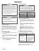
Operation WARNING Pressure Relief Procedure To reduce the risk of serious injury, including splashing in the eyes or on the skin, or injury from moving parts, fire, explosion, or electric shock, always follow this procedure when shutting off the system, when checking or servicing any part of the spray system, and whenever you stop operation. Flow Volume Range CAUTION The flow meter gear can be damaged if it rotates at too high a speed. To avoid high speed rotation, open the fluid valve gradually.
Maintenance CAUTION CAUTION Do not immerse the meter in solvent. Solvent could damage the meter’s electrical components. Excessively long air purges can over-speed the flow meter gears and cause over-heating of the gears and gear shaft. This can result in premature gear and shaft failure. NOTE: Clean the outside of the meter with a soft cloth dampened in a compatible solvent as needed.
Maintenance Cleaning or Servicing the Meter Chamber WARNING Installing and servicing this equipment requires access to parts that may cause electric shock or other serious injury if the work is not performed properly. Do not install or service this equipment unless you are trained and qualified. CAUTION To avoid damaging the shafts (5), keep the housings parallel to each other when separating them; do not rock the housings from side to side.
Maintenance Model PPM 3050 shown Models PPM 3050H, 3100H, & 3100H Sensor Device and Bolt 1 9 1 13 2 B 8 4 5 A 10 3 11 12 A B 12 11 10 01384 Fig.
Parts Use Only Genuine Graco Parts and Accessories Model PPM 3050 Part No. 235–587 1 9 2 8 5 4 3 12 10 11 11 10 12 01384 Ref. No. 1 2 Part No. Description 110–571 ELECTRONIC SENSOR HOUSING, upper; not a replacement part HOUSING, lower; not a replacement part GEAR SHAFT 3 4 5 12 110–573 110–575 308-243 Qty. 1 1 1 2 2 Ref. No. Part No.
Parts Use Only Genuine Graco Parts and Accessories Model PPM 3100 Part No. 235–588 1 9 2 8 5 4 3 12 10 11 11 10 12 01385 Ref. No. 1 2 Part No. Description 110–571 ELECTRONIC SENSOR HOUSING, upper; not a replacement part HOUSING, lower; not a replacement part GEAR SHAFT 3 4 5 110–574 110–576 Qty. 1 1 1 2 2 Ref. No. Part No.
Parts Use Only Genuine Graco Parts and Accessories Model PPM 3550 Part No. 235–592 1 9 2 8 5 4 3 12 10 11 11 10 12 01535 Ref. No. 1 2 Part No. Description 110–571 ELECTRONIC SENSOR HOUSING, upper; not a replacement part HOUSING, lower; not a replacement part GEAR SHAFT 3 4 5 14 110–583 110–584 308-243 Qty. 1 1 1 2 2 Ref. No. Part No.
Parts Use Only Genuine Graco Parts and Accessories Model PPM 3050H Part No. 235–593 1 9 13 2 8 5 4 3 12 10 11 11 10 12 01536 Ref. No. 1 2 Part No. Description 110–581 ELECTRONIC SENSOR HOUSING, upper; not a replacement part HOUSING, lower; not a replacement part GEAR SHAFT PIN, locating; not shown 3 4 5 7 110–573 110–575 110–579 Qty. 1 1 1 2 2 1 Ref. No. Part No. Description 8 9 10 110–588 110–580 110–586 11 12 13 110–587 185–885 105–776 O-RING; PTFE SCREW ADAPTOR; M12 x 1.
Parts Use Only Genuine Graco Parts and Accessories Model PPM 3100H Part No. 235–594 1 9 13 2 8 5 4 3 12 10 11 11 10 12 01537 Ref. No. 1 2 Part No. Description 110–581 ELECTRONIC SENSOR HOUSING, upper; not a replacement part HOUSING, lower; not a replacement part GEAR SHAFT PIN, locating; not shown 3 4 5 7 16 110–574 110–576 110–579 308-243 Qty. 1 1 1 2 2 1 Ref. No. Part No.
Parts Use Only Genuine Graco Parts and Accessories Model PPM 3550H Part No. 235–589 1 9 13 2 8 5 4 3 12 10 11 11 10 12 01535 Ref. No. 1 2 Part No. Description 110–581 ELECTRONIC SENSOR HOUSING, upper; not a replacement part HOUSING, lower; not a replacement part GEAR SHAFT PIN, locating; not shown 3 4 5 7 110–583 110–584 110–579 Qty. 1 1 1 2 2 1 Ref. No. Part No. Description 8 9 10 110–588 110–580 110–586 11 12 13 110–587 185–885 105–776 O-RING; PTFE SCREW ADAPTOR; M12 x 1.
Accessories Use Only Genuine Graco Parts and Accessories Meter Mounting Bracket 188–330 Connector 111–972 For mounting the meter to a wall or table. 7300 psi (511 bar) Maximum Working Pressure For connecting between flow meter adapter and nut 111–969. See page 4. PTFE o-ring face seal. 1/4 npt(mbe) Fluid Filter 223–160 5000 psi (350 bar) Maximum Working Pressure With stainless steel bowl and polyethylene support NOTE: Filter 223–160 has a 60 mesh screen.
Accessories Use Only Genuine Graco Parts and Accessories PPD 200 Remote Display PPD 200 Remote Display For use with Flow Meters Located in Class , Division 1 Hazardous Locations For use with Flow Meters Located in Class , Division 1 Hazardous Locations PPD 200 PART NO. FOR USE WITH METER MODEL NO. PPD 200 PART NO. FOR USE WITH METER MODEL NO.
Dimensions DIM. A 1/4 npt(f) inlet/outlet DIM. A DIM. B DIM. B DIM. C DIM. C DIM. D DIM. D 1/4 npt(f) inlet/outlet 01538 01382 Model No. Dim. A Dim. B Dim. C Dim. D PPM 3050 4.24 in. (107.70 mm) 2.00 in. (50.80 mm) 3.33 in. (84.58 mm) 5.90 in. (149.86 mm) PPM 3100 4.36 in. (110.74 mm) 2.16 in. (54.86 mm) 3.33 in. (84.58 mm) 5.90 in. (149.86 mm) PPM 3550 4.83 in. (122.68 mm) 2.63 in. (66.80 mm) 3.33 in. (84.58 mm) 5.90 in. (149.86 mm) PPM 3050H 5.10 in. (129.54 mm) 2.00 in.
Technical Data Maximum Working Fluid Pressure Flow Meter Inlet/Outlet Size without Connector Models PPM 3050, 3100, 3550 . 2000 psi (140 bar) Models PPM 3050H, 3100H, 3550H . . . . . 3000 psi (210 bar) Models PPM 3050, 3100, 3550 . . . . . . . . 1/4 bsp(m) Models PPM 3050H, 3100H, 3550H . . M12 x 1.5(m) Maximum Fluid Temperature Flow Range Models PPM 3050/3050H . . . . . . . 0.01–0.5 gal/min (38–1900 cc/min) Models PPM 3050, 3100, 3550 . . . 180_ F (80_ C) Models PPM 3050H, 3100H, 3550H . . . . . .
Safety Barrier Specifications WARNING To maintain intrinsic safety of your installation, only replace the Stahl barrier fuse with 160 mA replacement fuse, Stahl Part No. 011239. Stahl Model No. 9002/13–280–110–00 R. Stahl, Inc. Intrinsic Safety Barrier Outputs are Intrinsically Safe for Class I, Division 1, Groups A, B, C, D at 40 C. NOTE: This barrier is included with Graco PPD 200 Remote Displays 235–613, 235–614, and 235–615.
Notes
The Graco Warranty and Disclaimers WARRANTY Graco warrants all equipment manufactured by it and bearing its name to be free from defects in material and workmanship on the date of sale by an authorized Graco distributor to the original purchaser for use. As purchaser’s sole remedy for breach of this warranty, Graco will, for a period of twelve months from the date of sale, repair or replace any part of the equipment proven defective.