
User's Manual

Installation
To
reduce the risk of fire, explosion, or electric
shock, all electrical equipment must only be
installed by a qualified electrician.
Never install Models PPM 3050, 3100, and 3550 in
a Class
I
, Division 1 hazardous location. Only Mod
-
els PPM 3050H, 3100H, and 3550H are suitable for
Class
I
, Division 1 hazardous location.
WARNING
Dust and Foreign Matter
Avoid
allowing dust or foreign matter from entering the
flow meter by taking the following precautions:
Thoroughly flush the fluid supply lines before
installing the flow meter
.
When installing fittings, make sure that no sealing
tape overlaps into the inside of the pipe.
Install a 100 mesh fluid filter upstream of the flow
meter
. See
Accessories.
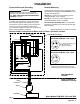
Installing the Flow Meter
NOTE: Flow
volume can only be measured at the lo
-
cation where the flow meter is installed.
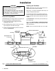
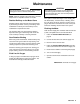
Refer to Fig. 1 to locate and install the flow meter
, con
-
nectors, and fluid shutof
f valves.
The shutof
f valves allow you to isolate the meter for
service. The gland, nut, and female connector shown
in Fig. 1 will ease removal of the flow meter from the
fluid line.
See
Accessories
to order these parts and other sys
-
tem components.
Refer to the
T
echnical Data
and
Dimensional Draw
-
ings
for dimension, inlet/outlet size, temperature and
other specifications.
NOTE:
Do not use more than 200 ft. (61 m) of cable.
Fig. 1
Electronic
Sensor Device
(Model PPM
3550H shown)
Flow Meter
Fluid Shutoff Valve
on inlet side
Fluid Shutoff Valve
on outlet side
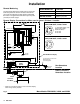
01387
Flow Meter
Fluid Line
*Nut
*Gland
*Male
Connector
Fluid Line
Cable
Male x Female
Connector
Provided with Meter
*Not provided. See
Accessories
to order
.
Ground
Sheath
TYPICAL RIGID TUBING INSTALLATION