INSTRUCTIONS-PARTS LIST This manual contains important warnings and information. READ AND KEEP FOR REFERENCE. 308–287 Rev. C Supersedes Rev. B First choice when and PCN C quality counts. INSTRUCTIONS PRO Pulse Electronic Volumetric Flow Meter For use with Plural Component Precision Mixing Systems This meter is designed to be used in a Class I, Group D hazardous environment 2800 psi (19.6 MPa, 196 bar) Maximum Working Fluid Pressure 50 psi (350 kPa, 3.5 bar) Maximum Working AirPressure Part No.
Table of Contents Warnings . . . . . . . . . . . . . . . . . . . . . . . . . . . . . . . . . . . . . . 2 Installation . . . . . . . . . . . . . . . . . . . . . . . . . . . . . . . . . . . . 4 Operation . . . . . . . . . . . . . . . . . . . . . . . . . . . . . . . . . . . . . 6 Maintenance . . . . . . . . . . . . . . . . . . . . . . . . . . . . . . . . . . . 7 Troubleshooting . . . . . . . . . . . . . . . . . . . . . . . . . . . . . . . . 8 Service . . . . . . . . . . . . . . . . . . . . . . . . . . . . . .
WARNING EQUIPMENT MISUSE HAZARD INSTRUCTIONS Equipment misuse can cause the equipment to rupture, malfunction, or start unexpectedly and result in a serious injury. D This equipment is for professional use only. D Read all the instruction manuals, tags, and labels before operating the equipment. D Use the equipment only for its intended purpose. If you are uncertain about usage, call your Graco distributor. D Do not alter or modify this equipment. Use only genuine Graco parts and accessories.
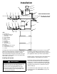
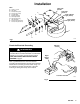
Installation L M R S B2 A C D G E NON-HAZARDOUS AREA H HAZARDOUS AREA F N A B1 C D P E J K KEY A B Air Supply Line Bleed-Type Air Supply Line Shut-off Valve (required) C Air Line Filter D Air Line Lubricator E Air Line Regulator F Pump G Fiber Optic Cable H Flow Meter J Fluid Supply Line K Fluid Supply L Main Power Switch M Pendant N Pump Grounding Wire (required) P Fluid Manifold R 115V 60 Hz Electrical Supply S Controller 01848 The PRO Pulse Volumetric Flow Meter is designed to detect t
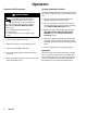
Installation KEY A B C D E F G H J K L Tubing, 1/4” OD Nut (nylon) Ferrule, back (nylon) Ferrule, front (nylon) Air Inlet Fitting Electrical Chassis Fiber Optic Cables Gear Housing Assy. Nut (aluminum) Ferrule, back (aluminum) Ferrule, front (aluminum) Fiber Optic Sender 1 Fiber Optic Sender 2 F Power Indicator Light (Yellow) L K J Flow Indicator Light (Green) E H D C G B A 01849 Fig.
Operation Pressure Relief Procedure WARNING INJECTION HAZARD Fluid under high pressure can be injected through the skin and cause serious injury. To reduce the risk of an injury from injection, splashing fluid, or moving parts, follow the Pressure Relief Procedure whenever you: are instructed to relieve the pressure, stop operating, or check or service any of the system equipment. 1. Turn off the air supply to the meter. 2. Allow air to exhaust out of the exhaust air port. 3.
Maintenance CAUTION Do not immerse the meter in solvent. Solvent could damage the meter’s electrical components. 1. Clean the fluid and air line filters daily. Flushing the Meter WARNING To reduce the risk of serious injury whenever you are instructed to relieve pressure, always follow the Pressure Relief Procedure on page 6. 2. Clean the outside of the meter with a soft cloth dampened in a compatible solvent as needed. 1. Relieve the pressure. 3.
Troubleshooting WARNING Before servicing this equipment always make sure to relieve the pressure. Installing and servicing this equipment requires access to parts that may cause electric shock or other serious injury if the work is not performed properly. Do not install or service this equipment unless you are trained and qualified. To reduce the risk of serious injury whenever you are instructed to relieve pressure, always follow the Pressure Relief Procedure on page 6.
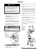
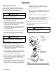
Service 2. Disconnect the 3-pin connector (J) from the square pins (H). WARNING Installing and servicing this equipment requires access to parts that may cause electric shock or other serious injury if the work is not performed properly. Do not install or service this equipment unless you are trained and qualified. 3. Carefully pull the alternator (4) away from the top housing.
Service Replacing Worn Bearings A repair kit is available to service the bearings. An asterisk after the description or reference letter indicates a part included with the repair kit. See page 11 to order the proper kit for your meter model. 3. Install the o-ring (M*), washers (K*), and gear assemblies (L*). Be sure to install the gears on their proper pegs. See Fig. 5. 4. Press the gear housings together and secure them with the four screws (N). Torque the screws to 7.5 ft-lbs (10 N m).
Service Removing Bearings Installing Bearings KEY KEY L T* V* W L P* R* S* T* U Gear Assembly Bearing Tool Bearings and Spacers Support *T Gear Bearing Inner Spacer Outer Spacer Bearing Tool Flat Surface *T R* L ÉÉ ÉÉ ÉÉ ÉÉ ÉÉ ÉÉ P* V *S W L ÉÉÉ ÉÉÉ ÉÉÉ ÉÉÉ ÉÉÉ ÉÉÉ P* U 0968 Fig. 6 0969 Fig. 7 Parts Bearing Repair Kit 223–276 K T P For Meter Model 235–402, with 0.
Parts Part No. 235–402, Series A Part No. 235–403 0.1 cc per tooth fluid volume flow with 0.
Parts Part No. 235–402, Series A 0.1 cc per tooth fluid volume flow Part No. 235–403, Series A 0.4 cc per tooth fluid volume flow Ref No. Part No. 1 1a 1b 2 2a 3 4 4a 5 6 7 8 9 111–073 111–070 224–277 186–924 224–276 224–603 110–073 186–852 111–157 186–853 110–420 111–308 Description Qty. GEAR HOUSING ASSY; Ordering information below; Includes replaceable items 1a & 1b . O-RING, fluid housing; PTFE . O-RING, fluid ports; PTFE CHASSIS ASSY, bottom; Includes item 2a .
Accessories Fiber Optic Cables Fluid Manifold Fiber Optic Cable Assembly For connection between the controller and flow meter. Contact your local Graco representative to order proper manifold. PART NO. LENGTH 224–690 224–691 224–692 224–693 224–694 224–695 224–696 6 ft (1.8 m) 15 ft (5 m) 25 ft (8 m) 36 ft (11 m) 50 ft (15 m) 75 ft (23 m) 100 ft (30.5 m) Fiber Optic Cable Extender For connection between the flow meter and bulkhead connector or between two bulkhead connectors. PART NO.
Dimensions DIM. A Part No. Dim. A Dim. B Dim. C 235–402 4.25 in (108 mm) 4.10 in. (104 mm) 4.44 in. (113 mm) 235–403 4.25 in (108 mm) 4.25 in. (108 mm) 4.50 in. (114 mm) DIM. B DIM. C 01847 Technical Data Category Data Maximum Working Fluid Pressure 2800 psi (19.6 MPa, 196 bar) Maximum Working Air Pressure 50 psi (350 kPa, 3.5 bar) Fluid Pressure Operating Range 0–2800 psi (0–19.6 MPa, 0–196 bar) Air Pressure Operating Range 20–50 psi (140–350 kPa, 1.4–3.
The Graco Warranty Graco warrants all equipment listed in this manual which is manufactured by Graco and bearing its name to be free from defects in material and workmanship on the date of sale by an authorized Graco distributor to the original purchaser for use. With the exception of any special extended or limited warranty published by Graco, Graco will, for a period of twelve months from the date of sale, repair or replace any part of the equipment determined by Graco to be defective.