
User's Manual

14 308345
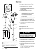
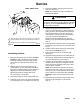
Service
06240C
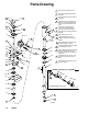
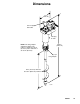
4
8
7
3
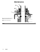
Fig. 9
25
41
14a
14
B
24
6
Torque oppositely and evenly to 60 to 70 in-lb (6.8 to 7.9 Nm).
Apply PTFE spray lubricant to inside lip of bearing nut before
you install it.
Apply PTFE spray lubricant to siphon tube (4) inlet end and to
top 6 in. (150 mm) of helix tube before you install them.
1
1
2
2
3
Model 236629 shown
3
Detail A
35
7 Ref
Detail B
14
3
Removing the Siphon and Helix Tubes
1. Remove the bearing nut (8). See Fig. 9.
2. Remove the two diagonal socket-head screws (24)
and lockwashers (25) protruding from the top of
the siphon cover (6).
3. Remove the siphon tube (4) as follows:
a. Rest the mixer on its side on the drive belt
housing so the inlet is lower than the outlet.
This orientation prevents fluid from running
into the bearing and drive belt area.
b. Pull up on the fluid outlet fitting (41) to remove
the siphon tube (4).
4. Remove the three hex-head screws (14a) from the
bushing (14), and install the screws into the bush-
ing’s threaded holes as shown in Detail A of Fig.
9. Tighten the screws evenly to loosen the bushing
from the helix tube (7).
5. Pull the helix tube (7) through the bottom of the
mixer housing (3).
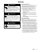
Removing the Drive Belt
NOTE: Replace the drive belt (15) if it is cracked or
worn.
WARNING
To avoid static electricity buildup and possible
sparking, which could cause fire and explosion,
replace the drive belt with a genuine ESD rated
and marked belt only (Graco Part No. 112552).
1. Remove the siphon tube (4) and helix tube (7) as
instructed above.
2. Remove the eight screws (27) and the drive belt
cover (2). See Fig. 10.
3. Remove the three hex-head screws (14a) and the
bushing (14).
4. Slide the drive belt (15) over the smaller pulley
(12). Then remove the larger pulley (13) and the
drive belt (15) as shown in Fig. 10.