Instructions – Parts List Parts CARBON STEEL Dura–Flot 1100 Pumps 308357G With Severe–Duty Rod and Cylinder Part No. 236932 Pump, Series A, 74:1 Ratio with Premiert Air Motor and 236478 Displacement Pump 50.0 MPa, 500 bar (7252 psi) Maximum Fluid Working Pressure 0.67 MPa, 6.7 bar (97 psi) Maximum Air Input Pressure Important Safety Instructions Read all warnings and instructions in this manual. Save these instructions. See page 2 for Table of Contents. 9589A GRACO INC.ąP.O.
Table of Contents Warnings . . . . . . . . . . . . . . . . . . . . . . . . . . . . . . . . . . . . . . 2 Installation . . . . . . . . . . . . . . . . . . . . . . . . . . . . . . . . . . . . . 6 Operation/Maintenance . . . . . . . . . . . . . . . . . . . . . . . . . 8 Troubleshooting Chart . . . . . . . . . . . . . . . . . . . . . . . . . 11 Service . . . . . . . . . . . . . . . . . . . . . . . . . . . . . . . . . . . . . . 12 Required Tools . . . . . . . . . . . . . . . . . . . . . . . . . . . .
WARNING SKIN INJECTION HAZARD Spray from the gun, hose leaks, or ruptured components can inject fluid into your body and cause extremely serious injury, including the need for amputation. Fluid splashed in the eyes or on the skin can also cause serious injury. D Fluid injected into the skin might look like just a cut, but it is a serious injury. Get immediate surgical treatment. D Do not point the gun/valve at anyone or at any part of the body. D Do not put your hand or fingers over the spray tip/nozzle.
WARNING FIRE AND EXPLOSION HAZARD Improper grounding, poor ventilation, open flames or sparks can cause a hazardous condition and result in a fire or explosion and serious injury. D Ground the equipment and the object being sprayed/dispensed. Refer to Grounding on page 5. D If there is any static sparking or you feel an electric shock while using this equipment, stop spraying immediately. Do not use the equipment until you identify and correct the problem.
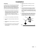
Installation Grounding To reduce the risk of static sparking, ground the pump, object being sprayed , and all spray/dispensing equipment used or located in the spray/dispensing area. Check your local electrical code for detailed grounding instructions for your area and type of equipment. Be sure to ground all of this spray/dispensing equipment. 1. Pump: loosen the grounding lug locknut (W) and washer (X). Insert one end of a 1.
Installation NOTE: Reference numbers and letters in parentheses in the text refer to the callouts in the figures and the parts drawing. NOTE: Accessories are available from your Graco representative. If you supply your own accessories, be sure they are adequately sized and pressure-rated to meet the system’s requirements. Fig. 2 is only a guide for selecting and installing system components and accessories. Contact your Graco distributor for assistance in designing a system to suit your particular needs.
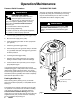
Installation ASSEMBLE THE PUMP D An air line lubricator (D) provides automatic air motor lubrication. Assemble the displacement pump (105) to the air motor (101) as instructed on pages 12–13. D A bleed-type master air valve (E) is required in your system to relieve air trapped between it and the air motor when the valve is closed (see the WARNING at left). Be sure the bleed valve is easily accessible from the pump, and is located downstream from the air regulator. Order Part No. 112730.
Operation/Maintenance Pressure Relief Procedure WARNING SKIN INJECTION HAZARD Fluid under high pressure can be injected through the skin and cause serious injury. To reduce the risk of an injury from injection, splashing fluid, or moving parts, follow the Pressure Relief Procedure whenever you: D D D D are instructed to relieve the pressure, stop spraying/dispensing, check or service any of the system equipment, or install or clean the spray tip/nozzle.
Operation/Maintenance Starting and Adjusting the Pump 1. Refer to Fig. 2 on page 6. Connect the suction kit (T) to the pump’s fluid inlet, and place the tube into the fluid supply. 2. Be sure the air regulator (F) is closed. Then open the pump’s bleed-type master air valve (E). Hold a metal part of the spray gun (S) firmly to the side of a grounded metal pail and hold the trigger open. Now slowly open the air regulator until the pump starts. 3.
Notes 10 308357
Troubleshooting Chart WARNING To reduce the risk of serious injury whenever you are instructed to relieve pressure, always follow the Pressure Relief Procedure on page 8. Before servicing this equipment always make sure to Relieve the Pressure. Check all possible problems and solutions before disassembling the pump. PROBLEM CAUSE SOLUTION Pump fails to operate. Restricted line or inadequate air supply; Clear; increase air supply. closed or clogged valves. Check that valves are open.
Service WARNING To reduce the risk of serious injury whenever you are instructed to relieve pressure, always follow the Pressure Relief Procedure on page 8. REQUIRED TOOLS D D D D D D D D D D Set of adjustable wrenches 15/16 in. (or 23 mm) socket wrench Large pipe wrench Torque wrench Rubber mallet O-ring pick Large vise Thread lubricant Thread sealant LoctiteR 2760t or equivalent DISCONNECTING THE DISPLACEMENT PUMP 1. Flush the pump, if possible.
Service V 3 101 102 2 104 108 103 2 1 1 107 2 1 106 1 105 U 1 Torque to 129–142 N.m (95–105 ft–lb) 2 Torque to 312–340 N.m (230–250 ft–lb) 3 Apply LoctiteR 2760t (or equivalent) to threads. 9592A Fig.
Service 5. Lift the cylinder (11), displacement rod (1), and piston assembly off the intake housing (16). Remove the ball guide (27) from the intake housing, and inspect the guide surfaces. See Fig. 6. DISPLACEMENT PUMP SERVICE Disassembly When disassembling the pump, lay out all the removed parts in sequence, to ease reassembly. 6. Using a rubber mallet, drive the displacement rod (1) and piston assembly out the bottom of the cylinder (11) until the piston comes free.
Service 9. Examine the displacement rod (1) for scratches or other damage. Only if the rod needs replacement, unscrew it from the piston ball housing (12), using an adjustable wrench on the flats of the rod. 1 10. Remove and inspect the glands and v-packings (P) from the piston seat housing (14). Inspect the ball (13), and the seat (E) and guides (F) on the housing for wear or damage. See Fig. 8. 1 11. Unscrew the packing nut (2) from the outlet housing (9).
Service Reassembly 1. If it was necessary to remove the piston ball housing (12) from the displacement rod (1), clean the threads of the rod and the ball housing, and apply thread sealant. Screw the ball housing onto the rod, hand tight. Place the flats of the piston ball housing in a vise and torque the rod to 386–407 N.m (285–300 ft–lb). See Fig. 8. 2.
Service 1 Torque to 129–142 N.m (95–105 ft–lb). 8 See Throat Packing Detail at left. 2 Torque to 522–542 N.m (385–400 ft–lb). 9 See Piston Packing Detail at left. 3 Torque to 386–407 N.m (285–300 ft–lb). 10 4 Lubricate. Torque to 244–264 N.m (180–195 ft–lb). 5 Apply thread sealant. 6 Lips face up. 7 Lips face down.
Parts Part No. 236932 Pump, Series A 74:1 Ratio, with Premier Air Motor Ref. No. Part No. Description 101 222800 102{ 103{ 104{ 105 184583 184098 112887 236478 106{ 107{ 106166 184382 108{ 184129 AIR MOTOR, Premier See 308213 for parts ADAPTER, connecting rod NUT, coupling WRENCH, spanner PUMP, displacement See page 19 for parts NUT, hex; M16 x 2.0 ROD, tie; 380 mm (14.96 in.) shoulder to shoulder COLLAR, coupling { These parts are included in Connection Kit 235416.
Parts Displacement Pump 236478, Series A Ref No. Part No. 1 2 8Y 9 10* 11 12 13* 189317 222995 172479 237183 109499 190221 184513 100279 14 222951 Description Qty ROD, displacement; stainless steel PACKING NUT; carbon steel TAG, warning (not shown) HOUSING, outlet; ductile iron SEAL; PTFE CYLINDER; stainless steel HOUSING, ball, piston; carbon steel BALL, piston; chrome steel; 0.875 in. (22.2 mm) dia. HOUSING, seat, piston valve; stainless steel w/tungsten carbide seat 1 1 1 1 2 1 1 1 1 2 Ref No.
Repair Kits Standard Repair Kit 237166 (Leather Packings and PTFE Backup) Ref No. Part No. Description 3* 4* 5* 6* 109306 184201 184306 184251 V-PACKING; PTFE GLAND, female; carbon steel V-PACKING; leather GLAND, male; carbon steel Packing Conversion Kit 237168 (UHMWPE and Leather Packings) Qty 2 2 8 2 Ref No. Part No.
Technical Data (MODEL 236932 PREMIER PUMP) Category Data Ratio 74:1 Maximum fluid working pressure 500 bar (7252 psi) Maximum air input pressure 6.7 bar (97 psi) Pump cycles per 3.8 liters (1 gal.) 14 Maximum flow at 60 cycles/min. 15.9 liters/min (4.2 gpm) Air motor piston effective area 800 cm@ (124 in.@) Stroke length 120 mm (4.75 in.) Displacement pump effective area 11 cm@ (2.79 in.
Technical Data (MODEL 236932 PREMIER PUMP) Performance Charts: Premier Pumps To find Fluid Outlet Pressure (psi/MPa/bar) at a specific fluid flow (lpm/gpm) and operating air pressure (psi/MPa/bar): 1. Locate desired flow along bottom of chart. To find Pump Air Consumption (m#/min. or scfm) at a specific fluid flow (lpm/gpm) and air pressure (psi/MPa/bar): 1. Locate desired flow along bottom of chart. 2. Follow vertical line up to intersection with selected fluid outlet pressure curve (black).
Dimensions Mounting Hole Layout Premier Pumps G 135.0 mm (5.3 in.) 67.5 mm (2.7 in.) C 116.9 mm (4.6 in.) 87.9 mm (3.5 in.) A Three M16 x 2.0 Holes Three 3/8–16 Mounting Studs 101.5 mm (4.0 in.) 50.7 mm (2.0 in.) 9655A B D F E 9589A Pump Model A B C D E F G 236932 1146.9 mm (45.15 in.) 746.0 mm (29.37 in.) 400.9 mm (15.78 in.) 413.0 mm (16.26 in.) 2 in. npt(f) 1 in.
Graco Standard Warranty Graco warrants all equipment manufactured by Graco and bearing its name to be free from defects in material and workmanship on the date of sale by an authorized Graco distributor to the original purchaser for use. With the exception of any special, extended, or limited warranty published by Graco, Graco will, for a period of twelve months from the date of sale, repair or replace any part of the equipment determined by Graco to be defective.