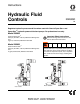
Instructions Hydraulic Fluid Controls 308395D EN Regulates hydraulic pressure and flow when used with Graco’s Dyna-Star™ and Power-Star™ hydraulic-powered lubricant pumps. For professional use only. Model 236864 Used with Dyna-Star™ 1500 psi (10.5 MPa, 105 bar) Maximum Working Pressure 3 gpm (11 liters/min) Maximum Flow Rate Important Safety Instructions Read all warnings and instructions in this manual. Save these instructions. Model 236865 Used with Power-Star™ 1500 psi (10.
Warnings Warnings The following warnings are for the setup, use, grounding, maintenance, and repair of this equipment. The exclamation point symbol alerts you to a general warning and the hazard symbols refer to procedure-specific risks. When these symbols appear in the body of this manual or on warning labels, refer back to these Warnings. Product-specific hazard symbols and warnings not covered in this section may appear throughout the body of this manual where applicable.
Warnings WARNING EQUIPMENT MISUSE HAZARD Misuse can cause death or serious injury. • Do not operate the unit when fatigued or under the influence of drugs or alcohol. • Do not exceed the maximum working pressure or temperature rating of the lowest rated system component. See Technical Data in all equipment manuals. • Use fluids and solvents that are compatible with equipment wetted parts. See Technical Data in all equipment manuals. Read fluid and solvent manufacturer’s warnings.
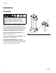
Installation Installation Grounding The equipment must be grounded to reduce the risk of static sparking and electric shock. Electric or static sparking can cause fumes to ignite or explode. Improper grounding can cause electric shock. Grounding provides an escape wire for the electric current. Z V W Pump: use ground wire and clamp (supplied). Loosen grounding lug locknut (W) and washer (V). Insert one end of a 12 ga (1.
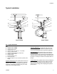
Installation Typical Installation C E L C L E A G J G K H J D K F F B H D Model 236864 Model 236865 FIG.
Installation Installation Notes Hydraulic Components NOTICE The hydraulic supply system must be kept clean at all times to reduce the risk of damaging the reciprocator hydraulic power supply. • • Always turn off the supply side valve (G) to avoid possible serious injury or component damage. See the Typical Installation on page 5. Blow out all hydraulic lines with air, flush thoroughly with solvent, and then blow out the air again before connecting the lines to the reciprocator.
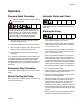
Operation Operation Pressure Relief Procedure Hydraulic Fluid Level Check Follow the Pressure Relief Procedure whenever you see this symbol. This equipment stays pressurized until pressure is manually relieved. To help prevent serious injury from pressurized fluid, such as skin injection, splashing fluid and moving parts, follow the Pressure Relief Procedure when you stop spraying and before cleaning, checking, or servicing the equipment.
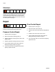
Repair Shutdown Always shut off the supply line shutoff valve (E) first, and then the return line shutoff valve (G). This is to prevent over pressurizing the reciprocator or its seals. When starting the hydraulic system, open the return line shutoff valve (G) first. See page 5. Repair Flow Control Repair 1. Relieve pressure, see page 7. There are two basic repairs to the hydraulic fluid control; pressure control repair and flow control repair. Pressure Control Repair 1. Relieve pressure, see page 7. 2.
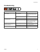
Troubleshooting Troubleshooting Problem Cause Solution No pressure on gauge, or low pressure on gauge Hydraulic power supply malfunction or mis-adjustment Adjust the hydraulic power supply. If the problem remains, refer to the hydraulic power supply instruction manual. Pressure reducing valve is backed out Adjust the pressure reducing valve. Can’t adjust pressure with the pressure reducing valve Clogged valve Clean the pressure reducing valve.
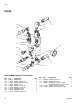
Parts Parts 111 112 1 110 102 103 109 105 108 113 Includes items 113a & 113b 104 113b 113a 110 106 107 103 Model 236864 Hydraulic Fluid Control Ref. 102 103 104 105 106 107 108 109 110 10 Part 108537 112714 112567 112578 112581 112705 112707 112708 112715 Description VALVE, ball HOSE, coupled, 3 ft GAUGE, pressure, fluid VALVE, ball SWIVEL, union, 90° SWIVEL, union, 90° ADAPTER, male ADAPTER, male HOUSE, couple, 3 ft Qty. 1 2 1 1 1 1 1 1 2 Ref.
Parts 111 105 112 104 110 109 102 108 113 113b Includes items 113a & 113b 103 113a 107 106 110 111 Model 236865 Hydraulic Fluid Control Ref. 102 103 104 105 106 107 108 109 110 Part 108537 112567 112579 112580 112705 112706 112708 112709 112715 308395D Description VALVE, ball GAUGE, pressure, fluid VALVE, ball SWIVEL, union, 90° SWIVEL, union, 90° SWIVEL, union, 90° ADAPTER, male ADAPTER, male HOSE, coupled, 3 ft Qty. 1 1 1 1 1 1 1 1 2 Ref.
Technical Data Technical Data Hydraulic Fluid Controls: Dyna-Star™ US Maximum fluid working pressure Pressure adjusting range Flow setting Maximum fluid temperature Weight Wetted materials Sound Pressure Metric 10.5 MPa, 105 bar 3.5-10.
Notes Notes 308395D 13
Graco Standard Warranty Graco warrants all equipment referenced in this document which is manufactured by Graco and bearing its name to be free from defects in material and workmanship on the date of sale to the original purchaser for use. With the exception of any special, extended, or limited warranty published by Graco, Graco will, for a period of twelve months from the date of sale, repair or replace any part of the equipment determined by Graco to be defective.