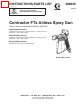
INSTRUCTIONS-PARTS LIST 308645 Rev. D This manual contains important warnings and information. READ AND KEEP FOR REFERENCE. INSTRUCTIONS Contractor FTx Airless Spray Gun 3600 psi (252 bar) MAXIMUM WORKING PRESSURE Model 238350, Series A Includes RACr DripLesst Guard, 515 size SwitchTipt, and 4-finger trigger. Model 824004, Series A Includes RACr DripLesst Guard, 515 size SwitchTipt, and 4-finger trigger.
Table of Contents Warnings . . . . . . . . . . . . . . . . . . . . . . . . . . . . . . . . . . . . . . 2 Installation/Operation . . . . . . . . . . . . . . . . . . . . . . . . . . . 5 System Requirements . . . . . . . . . . . . . . . . . . . . . . . . . . 5 How to Use the Trigger Safety Latch . . . . . . . . . . . . . 5 How to Use the Gun . . . . . . . . . . . . . . . . . . . . . . . . . . . 6 How to Adjust the Spray Pattern . . . . . . . . . . . . . . . . . .
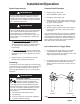
WARNING INJECTION HAZARD Spray from the gun, leaks or ruptured components can inject fluid into your body and cause extremely serious injury, including the need for amputation. Fluid splashed in the eyes or on the skin can also cause serious injury. D Fluid injected into the skin might look like just a cut, but it is a serious injury. Get immediate medical attention. D Do not point the gun at anyone or at any part of the body. D Do not put your hand or fingers over the spray tip.
WARNING FIRE AND EXPLOSION HAZARD Improper grounding, poor ventilation, open flames or sparks can cause a hazardous condition and result in a fire or explosion and serious injury. D If there is any static sparking or you feel an electric shock while using this equipment, stop spraying immediately. Do not use the equipment until you identify and correct the problem. D Provide fresh air ventilation to avoid the buildup of flammable fumes from solvents or the fluid being sprayed.
Installation/Operation System Requirements WARNING Keep the wallet-sized warning card provided with this gun with the operator at all times. The card contains important treatment information should an injection injury occur. Additional cards are available at no charge from Graco Inc. WARNING Be sure your system has a bleed-type master air valve (pneumatic pumps only) and a pressure drain valve.
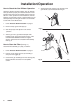
Installation/Operation How to Use the Gun 1. Connect a grounded fluid hose to the gun inlet. See Fig. 2 2. With no tip installed, start the pump. Flush the pump according to the instructions supplied with it. Prime the system with the fluid. 3. Follow the Pressure Relief Procedure on page 5. Be sure the gun trigger safety is engaged. See Fig. 1. 7. If adjusting the pressure does not give a good spray pattern, follow the Pressure Relief Procedure on page 5 and then try another tip size. 8.
Installation/Operation How to Clean the Spray Tip and Clear a Spray Tip Obstruction WARNING To reduce the risk of fluid injection or splashing in the eyes or on the skin, do not hold a hand, body or rag in front of the spray tip when cleaning or checking a clogged tip. Point the gun toward the ground or into a waste container when checking to see if the spray tip is cleared. DO NOT try to “blow back” paint; this is NOT an air spray gun.
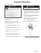
Installation/Operation How to Check the Gun Diffuser Operation 4. Apply lithium-base grease to the threads of the gun handle (14) and reassemble the gun. Check the diffuser operation weekly. The gun diffuser/ seat (A) breaks up spray and reduces the risk of fluid injection when the tip is not installed. Perform the test below. If it fails, replace the entire Needle Kit, Part No. 218070, as instructed on page 7.
Installation/Operation How to Flush the Gun WARNING ÄÄ To reduce the risk of serious bodily injury, including splashing fluid in the eyes or on the skin, or static electric discharge when flushing: D Be sure the entire system, including flushing pails, are properly grounded. D Remove the tip guard and spray tip. D Maintain metal to metal contact between the gun and the flushing pail. D Use the lowest possible pressure. Always flush the pump and the gun before the fluid being sprayed can dry in it.
Service 4. If the gun handle (6) was removed, hand tighten it into the fluid housing (26); it should fit easily. D 23 C 1 A 5. Adjust the needle before using the gun. Procedure below. 4 6. Be sure the trigger guard and tip guard are installed before using the gun. B Adjusting the needle (See Fig. 9) 1. Engage the gun safety latch. 05970 2. Hold the gun with the nozzle straight up. 1 Torque to 26–32 ft-lb (35–43 N.m) Fig. 8 3. Hold your finger against the trigger with light pressure.
Service Replace Swivel Reassembly (See Fig. 10) 1. Clean internal thread of handle (6). Disassembly 1. Follow Pressure Relief Procedure on page 5. 2. Push up on trigger guard (12) and swing trigger guard away from trigger (5). 3. Unscrew gun handle (6) from housing (26). Remove filter and clean in compatible solvent. 2. Install guard retainer (42), cushion o-ring (43) and swivel (15). 3. Apply PST pipe seal (included in Swivel Kit 238817) to external thread of swivel (15) that connects to handle (6).
Parts Drawing Model 238350, Series A Model 824004, Series A Model 239045, Series A 32 26 23 Included with 1 21 33 31 1 n40 18 22n n41 17 20 16 5 37 2 12 6 45 1 2 05962 42 45 43 15 12 308645 1 Purchase separately 2 Included with 239045
Parts List Model 238350, Series A; Model 824004, Series A Ref. No. Part No. Description 1 5 6 10Y 11Y 12 15 16 17n 218070 238199 195788 222385 187348 195495 238817 179750 218131 NEEDLE–DIFFUSER/SEAT KIT 4-FINGER TRIGGER (standard) HANDLE, round KIT, warning card COVER, warning TRIGGER GUARD SWIVEL, kit SPRING RETAINER FLUID FILTER ASSEMBLY Qty.
Accessories FILTERS 220222 Standard DripLesst Tip Guard. Order flat tip separately. See your distributor for available sizes. 222674 Heavy Duty RACR DripLesst Tip Guard. Order SwitchTip separately. See your distributor for available sizes. 3000 psi (210 bar) Maximum Working Pressure. Adequate filtering is important for a good surface finish and to minimize tip clogging. Elements are available in various mesh sizes.
Technical Data Maximum Working Pressure . . . . . . 3600 psi (252 bar) Fluid Orifice Size . . . . . . . . . . . . . . . 0.125 in. (3.18 mm) Wetted Parts . . . . . . . . . Stainless steel, Polyethylene, Aluminum, Polyurethane, Nylon, PTFE R Brass, Tungsten carbide, UHMW Weight . . . . . . . . . . . . . . . . . . . . . . . . . . . . . 17 oz. (482 g) Inlet . . . . . . . . . . . . . . . . . . . . . . . . . . 1/4 npsm(m)swivel Maximum Material Temperature . . . . . . .
Graco Warranty Graco warrants all equipment listed in this manual which is manufactured by Graco and bearing its name to be free from defects in material and workmanship on the date of sale by an authorized Graco distributor to the original purchaser for use. With the exception of any special extended or limited warranty published by Graco, Graco will, for a period of twelve months from the date of sale, repair or replace any part of the equipment determined by Graco to be defective.