Instructions–Parts List STAINLESS STEEL, WATERBASE-COMPATIBLE, HIGH PRESSURE Fluid Pressure Regulators 308647P EN For precise downstream pressure and flow control. Important Safety Instructions Read all warnings and instructions in this manual. Save these instructions. See page 2 for List of Models and Table of Contents. 06290 06288 Model 238890, 238892 (spring-operated) Model 238894 (air-operated) U.S. Patent No.
Table of Contents List of Models . . . . . . . . . . . . . . . . . . . . . . . . . . . . . . . . . . 2 Warnings . . . . . . . . . . . . . . . . . . . . . . . . . . . . . . . . . . . . . . 3 Installation . . . . . . . . . . . . . . . . . . . . . . . . . . . . . . . . . . . . . 6 Operation . . . . . . . . . . . . . . . . . . . . . . . . . . . . . . . . . . . . . 8 Troubleshooting . . . . . . . . . . . . . . . . . . . . . . . . . . . . . . . 10 Service . . . . . . . . . . . . . . . . . . . . . . . . . . . . .
Symbols Warning Symbol Caution Symbol WARNING CAUTION This symbol alerts you to the possibility of serious injury or death if you do not follow the instructions. This symbol alerts you to the possibility of damage to or destruction of equipment if you do not follow the instructions. WARNING EQUIPMENT MISUSE HAZARD Equipment misuse can cause the equipment to rupture or malfunction and result in serious injury. INSTRUCTIONS D This equipment is for professional use only.
WARNING SKIN INJECTION HAZARD Spray from the gun, leaks, or ruptured components can inject fluid into your body and cause extremely serious injury, including the need for amputation. Fluid splashed in the eyes or on the skin can also cause serious injury. D Fluid injected into the skin might look like just a cut, but it is a serious injury. Get immediate surgical treatment. D Do not point the gun at anyone or at any part of the body.
Notes 308647 5
Installation Multiple Circulating Spray Station M E F K Key A B C D E F G H J K L M N P Air regulator Bleed-type master air valve Pump Fluid filter and drain valve Main fluid supply line Gun fluid supply line Fluid regulator with fluid pressure gauge (H) Fluid pressure gauge Air-assisted airless spray gun Back pressure valve Fluid return line Main circulating line Fluid supply container Drain valve C A J B J L K G G H H 06461 N P D P Single Direct Spray Station C A B J G WARNING Do not u
Installation Spray gun: Ground through connection to a properly grounded fluid hose and pump. Grounding the System WARNING Fluid supply container: Follow your local code. FIRE AND EXPLOSION HAZARD Before operating the fluid pressure regulator, ground the system as explained below. Object being sprayed: Follow your local code. Solvent pails used when flushing: Follow your local code. Use only metal pails, which are conductive, placed on a grounded surface.
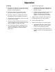
Operation Adjusting the System Pressure CAUTION D The new system must be cleaned and tested thoroughly before admitting fluid to the regulator to avoid contaminants clogging or damaging the regulator. D Always use the lowest possible air and fluid pressures for your application. High pressures can cause premature spray tip, regulator, and pump wear. NOTES: D The fluid pressure regulator controls pressure downstream from its outlet. D If you are using an accessory fluid pressure gauge (H in Fig.
Operation Flushing 4. Open the fluid regulator fully. D Flush before changing colors, before fluid can dry in the equipment, at the end of the day, before storing, and before repairing equipment. a. Spring Operated Regulators Only: Open the fluid regulator by turning the adjusting screw (10) fully clockwise. D Flush at the lowest pressure possible. Check connectors for leaks and tighten as necessary. b. Air Operated Regulator Only: Increase the air regulator setting to fully open the fluid regulator.
Troubleshooting WARNING NOTE: Check all possible solutions in the chart below before you disassemble the regulator. To reduce the risk of serious bodily injury, including skin injection, splashing in the eyes or on the skin, or injury from moving parts, always follow the Pressure Relief Procedure on page 5 whenever the pump is shut off, before installing, cleaning, adjusting, removing, or servicing the valve or any part of the system, and whenever you stop dispensing.
Service Service Kits For the Fluid Diaphragm Repair Kit, order Part 238747. Parts included in this kit are marked with an asterisk, for example (7*), in the Parts Drawings and Lists on pages 14 and 16. For the Cartridge Repair Kit, order Part 238748 for all models except 248090. Parts included in this kit are marked with a dagger, for example (3{), in the Parts Drawings and Lists on pages 14 and 16. For the Cartridge Repair Kit for 248090, order Part 248098.
Service Replacing the Fluid Diaphragms See Fig. 3, and follow the steps below. For parts that are not called out in Fig. 3, see the Parts Drawing on page 14. 1. Relieve the pressure, and remove the regulator from the fluid line. WARNING To reduce the risk of serious injury whenever you are instructed to relieve pressure, always follow the Pressure Relief Procedure on page 7. 6. Remove the o-ring (17) from the groove in the base housing (4), clean and inspect the base housing, and replace if necessary. 7.
Service Replacing the Cartridge See Fig. 3, and follow the steps below. For parts that are not called out in Fig. 3, see the Parts Drawing on page 14. CAUTION Handle the hard carbide parts, which are the ball (16), valve actuator (1), and valve seat (14), carefully to avoid damaging them. 1. Relieve the pressure. WARNING To reduce the risk of serious injury whenever you are instructed to relieve pressure, always follow the Pressure Relief Procedure on page 7. 2.
Parts Drawing Models 238889, 238890, 238891, and 238892 238889 with EZ Flush gauge port plug 238890 with fluid pressure gauge 238891 with EZ Flush gauge port plug 238892 with fluid pressure gauge Spring-Operated Regulator Spring-Operated Regulator 500 to 3000 psi (3.
Parts List Models 238889, 238890, 238891, and 238892 Ref. Part No. Description 1 2 3{ 4 5{ 6 7 8 9 * 238858 191577 191578 191579 191580 * 191583 113623 10 113624 11} 113625 ACTUATOR COVER, spring NUT, spring retainer BASE HOUSING; sst VALVE HOUSING; sst RETAINER, spring, guide PLUNGER, spring PLATE, backing BASE HOUSING SCREW, cap, socket-head; M10 x 1.5 x 70 ADJUSTING SCREW, cap, socket-head; M8 x 1.
Parts Drawing Models 238893, 238894, 248090, and 255072 }35 238893 with EZ Flush gauge port plug 238894 with fluid pressure gauge 248090 with fluid pressure gauge for LASD material 255072 High Resolution 32} }31 3 }2 }33 11} Air-Operated Regulator 6 7 }34 100 psi (0.7 MPa, 7 bar) Maximum Inbound Air Pressure }6 }28 500 to 4000 psi (3.
Parts List Models 238893, 238894, 248090, and 255072 Ref. No. Part No. Description 1 2} 3{n 4 * 191584 191577 191578 ACTUATOR 1 HOUSING ADAPTER 1 NUT, spring retainer 1 HOUSING, base, for Models 238893 and 238894 1 HOUSING, base, for Model 248090 1 HOUSING, base, for Model 255072 1 VALVE HOUSING, sst 1 VALVE HOUSING, for Model 255072 1 ROD, piston, for Models 238893, 238894, and 248090 1 ROD, piston, for Model 255072 1 PLUNGER, spring 1 PLATE, backing 1 BASE HOUSING SCREW, cap, socket-head; M10 x 1.
Parts Drawing Model 244734 244734 with EZ Flush gauge port plug 40 11} 5 Air-Operated Regulator, Full Range 100 psi (0.7 MPa, 7 bar) Maximum Inbound Air Pressure }28 500 to 4000 psi (3.4 to 28 MPa, 34 to 276 bar) Regulated Fluid Outlet Pressure }37 }30 8 8 }36 7* 3 }29 6 12* 13* 19* 3 1* }2 41 42 1 17* 4 6 }6 39 42 38 }22 3{ 41 2 14{ 7 18 1 Torque to 25 to 30 in-lb (2.8 to 3.4 NSm). 2 Torque to 140 to 160 in-lb (16 to 18 NSm). 3 Torque to 15 to 20 ft-lb (20 to 27 NSm).
Parts List Model 244734 Ref. No. Part No. Description 1 2} 3{ 4 5{ 6} 7 8 9 * 191584 191577 197952 191579 191585 * 191583 113623 ACTUATOR 1 HOUSING ADAPTER 1 NUT, spring retainer 1 REGULATOR HOUSING 1 VALVE HOUSING; sst 1 ROD, piston 1 PLUNGER, spring 1 PLATE, backing 1 BASE HOUSING SCREW, cap, socket-head; M10 x 1.5 x 70 4 SCREW, machine; 1/4–20 x 1.
Technical Data Model 238890 spring operated, with fluid pressure gauge M d l 238889 Model spring operated, with EZ Flush plug Model 238892 spring operated, with fluid pressure gauge M d l 238891 Model spring operated, with EZ Flush plug Maximum fluid inlet pressure 6000 psi (41 MPa, 414 bar) 6000 psi (41 MPa, 414 bar) 6000 psi (41 MPa, 414 bar) 6000 psi (41 MPa, 414 bar) Regulated fluid outlet pressure range 500–3000 psi (3.
Performance Chart Fluid Pressure Regulators, Models 238889 through 238894 and 248090 psi (MPa, bar) REGULATED (outbound) FLUID PRESSURE 6000 (41, 414) 5000 (34, 345) 4000 (28, 276) 3000 (21, 207) 2000 (14, 138) 1000 (7, 69) 0 gpm 0.0 (lpm) 0.5 1.0 1.5 2.0 (1.9) (3.8) (5.7) (7.6) FLUID FLOW Test Conditions Regulators tested in oil at 70_ F (21_ C) and at 6000 psi (41 MPa, 414 bar) inbound fluid pressure.
Notes 22 308647
Dimensional Drawings Models 238889 and 238891 with port plug Models 238890 and 238892 with gauge (spring operated) 3/8 npt inlet port A Height: 8.9 in. (225 mm) B Diameter of base housing: 2.65 in. (70 mm) 3/8 npt outlet port 1/4 npt gauge port A B 06290 1/4–20 UNC mounting holes, 1/2 in. (12 mm) deep (both sides) Model 238893 with port plug Model 238894 with gauge Models 248090 and 255072 with gauge and 1/2 npt inlet and outlet ports (air operated) A Height: 10.0 in.
Graco Standard Warranty Graco warrants all equipment referenced in this document which is manufactured by Graco and bearing its name to be free from defects in material and workmanship on the date of sale to the original purchaser for use. With the exception of any special, extended, or limited warranty published by Graco, Graco will, for a period of twelve months from the date of sale, repair or replace any part of the equipment determined by Graco to be defective.