Instructions/Parts List CycleFlo II Pneumatic Pump Controller 309004C Controls pump speed for precise batching, metering, and dosing of fluids at high or low pressures and flow rates. Not for use in explosive atmospheres. Important Safety Instructions Read all warnings and instructions in this manual. Save these instructions. Part No. 195265 120 psi (0.
Table of Contents Warnings . . . . . . . . . . . . . . . . . . . . . . . . . . . . . . . . . . . . . . . . . . . . . . . . . . . . . . . 3 General Description. . . . . . . . . . . . . . . . . . . . . . . . . . . . . . . . . . . . . . . . . . . . . . 5 Installation . . . . . . . . . . . . . . . . . . . . . . . . . . . . . . . . . . . . . . . . . . . . . . . . . . . . . . . 5 Electrical Connections . . . . . . . . . . . . . . . . . . . . . . . . . . . . . . . . . . . . . . . . . . . . Pneumatic Connections.
Warning Symbol This symbol alerts you to the possibility of serious injury or death if you do not follow the instructions. Caution Symbol This symbol alerts you to the possibility of damage to or destruction of equipment if you do not follow the instructions. Equipment Misuse Hazard Equipment misuse can cause the equipment to rupture or malfunction and result in serious injury. • This equipment is for professional use only.
Fire, Explosion, and Electric Shock Hazard Improper grounding, poor air ventilation, open flames, or sparks can cause a hazardous condition and resulting fire or explosion and serious injury. 4 309004 • Ground the equipment. • Proper grounding dissipates static electricity generated in the equipment. • This equipment is not intended for intrinsically safe areas. • Keep the dispense area free of debris, including solvent, rags, and gasoline.
General Description The CycleFlo II is a pneumatic pump controller that allows precise control over the cycle rate of the pump and therefor the flow rate. The pump cycle is initiated by a 120 volt signal. The pump cycle may be initiated by some other piece of equipment such as a timer or a pH controller. An isolation relay may be required in some installations. Always follow local and applicable electrical codes. The CycleFlo II will halt the pump cycle whenever the 120 volt signal is removed.
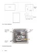
Fig.
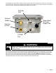
The integrated air valves, have a common air inlet (1/4" NPT) port and two outlet ports A and B (1/4” Tube) toward the front of the unit. The exhaust is silenced with a muffler. Do not exceed 120 psi at the air inlet to the unit. Refer to your pump owner’s manual for the maximum air pressure limit of the pump.
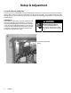
Setup & Adjustment Cycles Per Minute (CPM) Rate The pump cycle rate is adjustable to accommodate different pump sizes, varying product viscosities and product delivery speed. The pump cycle rate is measured in Cycles Per Minute (CPM), i.e. the number of times the pump performs a pump cycle in one minute. One pump cycle consists of a momentary pressurization of each one of the two diaphragms.
Operation Priming the Pump Prime the pump by applying a 120 Volt signal to the controller to allow the temporary operation of the pump. This cycle rate may be increased or decreased to facilitate pump priming. Shut off electrical supply before making adjustments. Operation Procedures The controller and pump are now ready for operation. The pump will cycle at the preset rate any time a 120 Volt signal is supplied to the controller.
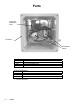
Parts Cycle rate adjustment relay Enclosure Air Solenoid Valves Part No. --------115414 115418 Description Enclosure Emblem (not shown – on front of unit) Cycle rate adjustment relay Air Solenoid Valves (Note: two valves are required per controller) Optional Accessories Part No. Description 102518 Cord Set, Electrical 115988 Tube, Polyurethane, 50 ft. 115606 Valve, Solenoid, 110 VAC, 8.5W ----- Not sold separately.
Typical Installation Diagram CycleFlo II Controller Chemical Injector Isolation Relay (recommended) Control Signal (24VDC) CycleFlo II Controller 110V on/off Compressed Air In On Off 110 VAC Solenoid Valve #1 Solenoid Valve #2 Air Supply Solenoid Valve *Monitor / Controller Husky 1040 Metering Pump Out Flow Controller sends an on/off signal (24VDC) to the isolation relay to control power to the CycleFlo II.
Typical Installation Diagram CycleFlo II Controller Control ON/OFF signal (110VAC) Compressed Air In Diaphragm Pump (Husky 205 shown) *PH Controller, Flow Controller Timer, etc. sends 110 VAC on/off signal to CycleFlo II *Flow Sensor *Provided by others 9410A Technical Data Power Requirements: 120Vac, 50/60 Hz, .2A, 24W Air Supply: 120 psi (0.
Mounting Hole Layout All mounting tabs may be placed in either position 7 3/8” (187 mm) 5” (127 mm) 7 3/8” (187 mm) 5” (127 mm) 13 309004
Graco Standard Warranty Graco warrants all equipment referenced in this document which is manufactured by Graco and bearing its name to be free from defects in material and workmanship on the date of sale by an authorized Graco distributor to the original purchaser for use. With the exception of any special, extended, or limited warranty published by Graco, Graco will, for a period of twelve months from the date of sale, repair or replace any part of the equipment determined by Graco to be defective.