Instructions Accu-Shot™ Electronic Grease Meter For high pressure grease dispense. For professional use only. Part No. 233807 English - measures in ounces and pounds Part No. 233933 Metric - measures in grams and kilograms 5000 psi (34.5 MPa, 345 bar) Maximum Working Pressure Important Safety Instructions Read all warnings and instructions in this manual. Save these instructions.
Warnings Warnings The following warnings are for the setup, use, grounding, maintenance, and repair of this equipment. The exclamation point symbol alerts you to a general warning and the hazard symbols refer to procedure-specific risks. When these symbols appear in the body of this manual or on warning labels, refer back to these Warnings. Product-specific hazard symbols and warnings not covered in this section may appear throughout the body of this manual where applicable.
Warnings WARNING FIRE AND EXPLOSION HAZARD When flammable fluids are present in the work area, such as gasoline and windshield wiper fluid, be aware that flammable fumes can ignite or explode. To help prevent fire and explosion: • Use equipment only in well ventilated area. • Eliminate all ignition sources, such as cigarettes and portable electric lamps. • Keep work area free of debris, including rags and spilled or open containers of solvent and gasoline.
Installation Installation A C D B F E FIG. 1: Typical Installation Key: A B C D E F Fluid shut-off valve Hose Hose reel fluid inlet hose Hose reel Accu-Shot electronic grease meter 2 in. swivel The installation shown in FIG. 1 is only a guide. The components shown are typical; however, it is not a complete system design. Contact your Graco distributor for assistance in designing a system to suit your particular needs. NOTICE This dispense valve is not designed for in-line installation.
Installation Grounding The equipment must be grounded to reduce the risk of static sparking and electric shock. Electric or static sparking can cause fumes to ignite or explode. Improper grounding can cause electric shock. Grounding provides an escape wire for the electric current.
Installation 7. Apply thread sealant to the male threads of the hose fitting (f), thread the hose fitting into the fitting (2) of the Accu-Shot, and tighten firmly. (FIG. 2) NOTE: Let the sealant cure to the manufacturer’s recommendations before the system is pressurized with grease. Grease Dispenser Components Refer to FIG. 3 for the following.
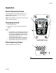
Operation Operation Before Dispensing Grease The partial delivery meter (a) must read zero. If the meter indicates a valve other than zero, press the RESET button (b). (FIG. 4) NOTE: The partial delivery total cannot be zero-set during the dispensing process. d e Dispensing Grease 1. Pull the dispense lever. 2. Release the lever once the grease has been dispensed.
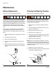
Maintenance Maintenance Battery Replacement Cleaning the Metering Chamber Refer to FIG. 5 for the following instructions. Refer to FIG. 6 for the following instructions. The display will remain off after the batteries have been replaced. This is because the Accu-Shot is equipped with a system that prevents powering the electrical components during battery replacement. To turn the LCD display on press the RESET button.
Maintenance Adjusting the Operating Lever Cleaning the Valve Refer to FIG. 7 for the following instructions. Refer to FIG. 8 for following instructions unless otherwise indicated. The Accu-Shot valve operating lever (36) can be adjusted using the adjustment set screw (41) and check nut (40). The Accu-Shot is shipped with the lever already locked and set and therefore does not normally require adjustment. It may need adjusting after being used for some time or when the valve is removed. 1.
Troubleshooting 12. Fit the plate gasket (26), the plate (25), and the housing (24) along with the screws (23). NOTE: Use compressed air to clean these parts. Grease all parts before reassembly. Avoid pinching the o-rings during reassembly. 13. Fit the set screw (41) and tighten the nut (40) on the lever (36). Adjust the set screw to correctly position the lever, referring to the Dimensions Drawing on page 13. 9.
Parts Parts 1 3 2 45 4 40 5 39 6 7 38 41 37 10 14 35 12 36 17 9 11 21 1 15 13 16 22 26 25 24 31 32 34 1 Torque to 4 to 6 in-lb (0.45 to 0.68 N.
Parts Parts Ref. 45 Part Description 200389 ADAPTER, hydraulic Qty. 1 Kit No. 245632, Electronic, English Repl. Kit Ref. 17 21 22 24 25 26 Description ELECTRONICS SCREW SPACER, key HOUSING PLATE, lcd GASKET, plate Qty. 1 3 1 1 1 1 Kit No. 245633, Valve Kit Ref. 9 10 11 12 13 14 15 16 Description Qty. RING, retaining BU 5 x 9 x 3 x 1.4 1 PTFE O-RING, 2012 Ø2.9 x 1.78 90SH 1 PINS, valve 1 BALL, Ø 1/8” 1 SEAT, valve 1 O-RING, 2037 Ø9.25x1.78 90SH 1 RING, retaining BG 12.5 x 9.9 x 1.
Technical Data Technical Data . Accu-Shot™ Electronic Grease Meter US Maximum fluid working pressure Storage temperature (range) Storage humidity (maximum) Operating Temperature (maximum) 5000 psi -4 to 158°F 140°F Metering system Accuracy Metric 34.
Graco Standard Warranty Graco warrants all equipment referenced in this document which is manufactured by Graco and bearing its name to be free from defects in material and workmanship on the date of sale to the original purchaser for use. With the exception of any special, extended, or limited warranty published by Graco, Graco will, for a period of twelve months from the date of sale, repair or replace any part of the equipment determined by Graco to be defective.