Instructions - Parts ™ Power-Lock Heated Hose 309572ZAF EN For use with plural component proportioners. For professional use only. Not approved for use in European explosive atmospheres. See page 3 for Maximum Fluid Working Pressure 130 psi (0.9 MPa, 9 bar) Maximum Air Working Pressure 180°F (82°C) Maximum Hose Operating Temperature Important Safety instructions. Read all warnings and instructions in this manual. Save these instructions. See page 3 for a list of part numbers.
Contents Power-Lock Hose Bundle Part Numbers . . . . . . . . 3 Whip Hoses . . . . . . . . . . . . . . . . . . . . . . . . . . . . . 3 Adapter Fittings . . . . . . . . . . . . . . . . . . . . . . . . . . 3 Standard 2 Component Hose . . . . . . . . . . . . . . . 4 RTD 2-Component Hose (for use with GCA Controlled Reactors) . . . . . . . . . . . . . . . . . . . 4 Airless 2 Component Hose . . . . . . . . . . . . . . . . . 5 Custom Application 2 Component Hose . . . . . . 5 Fluid Temperature Sensor (FTS) Kits .
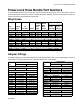
Power-Lock Hose Bundle Part Numbers Power-Lock Hose Bundle Part Numbers You need at least one 50 ft (15.2 m) main hose, one fluid temperature sensor (FTS), and one whip hose or one wire harness jumper (part no. 261821) to make a complete heated hose assembly. Be sure the selected hose meets your maximum pressure and hose diameter requirements. Whip Hoses Hose Length Assembly ft (m) ID in. (mm) Heated 2000 psi (13.8 MPa, 138 bar) 246050 10 (3) 1/4 (6) 249586 3 (0.9) 1/4 (6) 256407 6 (1.
Power-Lock Hose Bundle Part Numbers Standard 2 Component Hose Hose Length Assembly ft (m) ID FTS in.
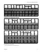
Power-Lock Hose Bundle Part Numbers Standard Braided Hose Length ID RTD Scuff Assembly ft (m) in. (mm) Cable Guard ✔ ✔ 24N001 50 (15.2) 1/2 (13) 3500 psi (24.1 MPa, 241 bar) ✔ ✔ 24K241 50 (15.2) 3/8 (10) ✔ 24Y241 50 (15.2) 3/8 (10) ✔ ✔ 24K395 50 (15.2) 3/8 (10) ✔ 24Y395 50 (15.2) 3/8 (10) ✔ 24U743 50 (15.2) 3/8 (10) ✔ ✔ 24N002 50 (15.2) 1/2 (13) ✔ ✔ 24N003 50 (15.
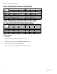
Power-Lock Hose Bundle Part Numbers Fluid Temperature Sensor (FTS) Kits “A” Side Part No. Inlet Outlet “B” Side FTS Probe Inlet Outlet -6 JIC -6 JIC -6 JIC 3/8 NPT FTS Probe 5000 psi (34.5 MPa, 345 bar) 261669 261670 -5 JIC -5 JIC -5 JIC 1/4 NPT ✔ ✔ 7250 psi (50 MPa, 500 bar) 24M943 1/2 npt (f) 1/2 (npt (f) ✔ 1/2 npt (f) 1/2 (npt (f) Fluid Temperature Sensor Kits (FTS, RTD; for use with GCA Controlled Systems) “A” Side Part No.
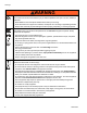
Warnings Warnings The following warnings are for the setup, use, grounding, maintenance, and repair of this equipment. The exclamation point symbol alerts you to a general warning and the hazard symbol refers to procedure-specific risk. When these symbols appear in the body of this manual, refer back to these Warnings. Product-specific hazard symbols and warnings not covered in this section may appear throughout the body of this manual where applicable.
Warnings WARNING WARNING TOXIC FLUID OR FUMES HAZARD Toxic fluids or fumes can cause serious injury or death if splashed in the eyes or on skin, inhaled, or swallowed. • Read MSDSs to know the specific hazards of the fluids you are using. • Store hazardous fluid in approved containers, and dispose of it according to applicable guidelines. • Always wear chemically impermeable gloves when spraying, dispensing, or cleaning equipment.
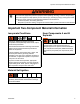
Important Two-Component Material Information WARNING WARNING PERSONAL PROTECTIVE EQUIPMENT You must wear appropriate protective equipment when operating, servicing, or when in the operating area of the equipment to help protect you from serious injury, including eye injury, hearing loss, inhalation of toxic fumes, and burns. This equipment includes but is not limited to: • Protective eyewear, and hearing protection.
Important Two-Component Material Information Moisture Sensitivity of Isocyanates Isocyanates (ISO) are catalysts used in two component foam and polyurea coatings. ISO will react with moisture (such as humidity) to form small, hard, abrasive crystals, which become suspended in the fluid. Eventually a film will form on the surface and the ISO will begin to gel, increasing in viscosity. If used, this partially cured ISO will reduce performance and the life of all wetted parts.
Installation Installation Description This hose must be used with an FTS and cable to provide grounding. The heated hose maintains proper fluid temperature while spraying. Fluid hoses are marked with red tape for ISO/hardener/minor volume side, blue tape for RES/resin/major volume side. Fittings have different sized threads to prevent incorrect connection, which can cause fluid crossover and permanently damage the hose. Hoses are 50 ft (15.2 m) or 25 ft (7.6 m) long.
Installation Connect Whip Hose to Gun or Gun Manifold Install hose in a helix configuration for: • • • • • Easy gun movement Large spraying motion Ability to spray in tight areas and odd angles Reduced operator fatigue Maximum hose life 1. Overlap A and B component hoses and assemble to gun or gun manifold fittings as shown in FIG. 1. 2. Tighten fittings to A and B component hoses. Ensure hose remains flat after fittings are tightened.
Installation Connect Heated Hoses 1. Lay heated hoses end to end, matching the color coding. Red for component A (ISO), blue for component B (RES). 2 B 1 TI2679B FIG. 3 Do not connect the main air supply at this time. A TI2678B FIG. 2 Some insulated heated hoses do not contain an air hose. 3. Connect air hoses (3). 2. Connect fluid hoses (1, 2) and tighten. See maximum torque specifications below and FIG. 3. Do not over-torque. Torque 1/4 in. (6.4 mm) and 3/8 in. (9.
Installation 4. Connect electrical wires. a. Ensure electrical wires ends are 5/8 in. (15.9 mm) long. If they are not, use a sharp scissors to strip all four wire ends to the correct length. See Strip Length Gauge for correct length. b. If wire is short of ferrule end, adjust strip length accordingly. If bare wire is protruding from ferrule, trim flush to ferrule end. See FIG. 6. Incorrect Strip Length Correct Incorrect TI9768a FIG. 6 This illustration is not to scale. 5/8 in. (0.
Installation 5. Pair electrical wires as follows: A-Hose to A-Hose; B-Hose to B-Hose. When connecting first hose section to proportioner, wire pairing does not make a difference. a. Insert one wire from heated hose into connector. Ensure that ferrule is mating with connector insert. See FIG. 8. d. Repeat sub-steps A through C for remaining wire pair. e. Re-torque all four setscrews to 60 in-lbs (6.78 N•m). When torqued to 60 in-lbs (6.78 N•m) setscrews will be approximately flush with connector. See FIG.
Installation 6. For non-RTD hoses only, connect cables (4). Slide insulator sleeves (S) over connection. Leave slack in cables as stress relief to prevent cable failure. S 4 TI2683B FIG. 11 7. For RTD 2-component hoses only, connect RTD cables (4) and CAN cables (5) if present. 4 5 TI18358a FIG. 12 8. Repeat for additional hoses. 9. See Connect FTS and Heated Dual Whip Hose, page 18, or Connect FTS with a Non-Heated Whip Hose or Remote Mix Manifold, page 20.
Installation 309572ZAF 17
Installation Connect FTS and Heated Dual Whip Hose NOTICE To prevent damage to probe, do not kink or excessively bend hose. Do not coil hose tighter than the minimum bend radius of 3 ft (0.9 m). Do not subject hose to excessive weight, impact, or other abuse. See FIG. 13 on page 19. For 1/2 in. (13 mm) ID fluid hoses only: Prior to connecting the FTS, remove the adapters from the proportioner fluid manifold and install them on the male ends of the hoses (1 and 2).
Installation Non-RTD Hoses 12 K To Gun 6b 5a 5b 5d To Proportioner 9 S 6a 4 S 2 8 1 5e 5c 3 TI17091b 12 RTD 2-Component Hoses 5d 5b 5a 6b K 6a 4 2 8 5c 3 5e TI18392b 1 14 FIG.
Installation Connect FTS with a Non-Heated Whip Hose or Remote Mix Manifold 3. Connect fluid hoses to FTS. NOTICE To prevent damage to probe, do not kink or excessively bend hose. Do not coil hose tighter than the minimum bend radius of 3 ft (0.9 m). Do not subject hose to excessive weight, impact, or other abuse. To use 1/2 in. (13 mm) ID fluid hoses, remove the adapters from the proportioner fluid manifold and install them in the FTS swivel inlets. 4. Install one connector (12) between wires.
Installation Check Hoses for Leaks 1. Grease with Fusion® grease and connect fluid hoses to proportioner fluid manifold (M). Red for hardener (ISO), blue for resin (RES). 4. Pressure check hose. See proportioner manual for priming instructions. After all lines are free of air, check for leaks. If there are leaks, relieve pressure as instructed in proportioner manual. Tighten connections, then pressurize again to ensure leaks have stopped. Relieve pressure.
Installation Protective Covering 1. Wrap all fluid hose connections with electrical tape. TI2681A FIG. 15 2. Fold wire back on hose to ensure adequate strain relief. Wrap all electrical connections and cable connections with electrical tape to protect them from pulling apart and abrasion. Leave CAN cable connector (if used) accessible at whip hose joint for connector to the Remote Display Module Kit (if ordered). 3.
Operation Operation Do not operate a coiled hose. A coiled hose creates uneven heat buildup which can result in hose rupture and cause serious injury, including fluid injection. Maximum hose operating temperature is 180°F (82°C). If using hose without an FTS, measure hose temperature to ensure it does not exceed 180°F (82°C). M 12 4 T 3 ti9878A FIG. 16 Hose must be properly supported to avoid excessive strain due to weight, bending, sharp edges, or stress caused by running over a roof edge. 3.
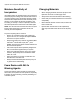
Maintenance Maintenance 1. Before disconnecting or repairing hoses, relieve all fluid pressure and shut off electrical power to proportioner. See proportioner operation manual. 2. Be sure fluid is cool before disconnecting hoses. Instructions for Replacing Individual A or B Hose Before disconnecting hoses, relieve all fluid pressure and shut off electrical power to proportioner. See proportioner operation manual. Disconnect electrical wire from connectors (12).
Parts Parts Using 261669 Fluid Temperature Sensor (JIC to JIC fittings) Whip Hose 12 Fluid Temperature Sensor 5b 5a 5d 2 9 4 6 8 3 5e 5c WL E Heated Fluid Hose Ref. Part 1 2 3 4 15B295 24F179 24J523 24J524 261669 5 5a 5b 5c 24V454 5d 127596 5e 127597 309572ZAF 1 Description Qty HOSE, component A (ISO); see 1 tables starting on page 4 HOSE, component B (RES); see 1 tables starting on page 4 HOSE, air; 50 ft (15.2 m) 1 HOSE, air; 25 ft (7.6 m) 1 CABLE, FTS; 50 ft (15.
Parts Using 24M943 Fluid Temperature Sensor (NPT to NPT fittings) Whip Hose Fluid Temperature Sensor 5b 15 12 5a 9 2 4 6 15 8 5c 3 Ti19091b Heated Fluid Hose Ref. Part 1 2 3 4 5 5a 5b 5c 6 15B295 24F179 24J523 24J524 24M943 8 9 15B280 12 261821 13▲ 15B679 ▲ 16M219 15★ 1 Description Qty HOSE, component A (ISO); see 1 tables starting on page 4 HOSE, component B (RES); see 1 tables starting on page 4 HOSE, air; 50 ft (15.2 m) 1 HOSE, air; 25 ft (7.6 m) 1 CABLE, FTS; 50 ft (15.
Parts Using 24K207 RTD 2-Component Hose Fluid Temperature Sensor (JIC to JIC fittings) Fluid Temperature Sensor 12 5d 2 Whip Hose 5a 5b 4 9 6 8 5c 5e 1 Heated Fluid Hose Ref. Part 1 2 3 4 5 5a 5b 5c 5d 5e 15B295 24N450 24K207 24V454 127596 127597 3 14 Description Qty HOSE, component A (ISO); see 1 tables starting on page 4 HOSE, component B (RES); see 1 tables starting on page 4 HOSE, air; 50 ft (15.2 m) 1 CABLE, RTD; 50 ft (15.2 m) 1 KIT, FTS, coupler 1 SENSOR, FTS-RTD 1 COUPLER 1 HOSE, air; 4.
Parts Using 24M944 RTD 2-Component Hose Fluid Temperature Sensor (NPT to NPT fittings) Whip Hose Fluid Temperature Sensor 12 5b 15 5a 15 2 9 4 6 15 8 5c 15 Heated Fluid Hose Ref. Part 1 1 14 Description Qty HOSE, component A (ISO); see 1 tables starting on page 4 2 HOSE, component B (RES); see 1 tables starting on page 4 3 15B295 HOSE, air; 50 ft (15.2 m) 1 4 24N450 CABLE, RTD; 50 ft (15.2 m) 1 5 24M944 KIT, FTS, coupler 1 5a SENSOR, FTS-RTD 1 5b COUPLER 1 5c HOSE, air; 3.75 in. (95.
Parts Using 261670 Fluid Temperature Sensor (JIC to NPT fittings) Fluid Temperature Sensor 5 5b 5a Heated Fluid Hose 4 1 5d 5c 12 2 Ref. 1 Part 2 4 5 24J523 24J524 261670 5a 5b 156823 117595 309572ZAF Description Qty HOSE, component A (ISO); see 1 tables starting on page 4 HOSE, component B (RES); see 1 tables starting on page 4 CABLE, FTS; 50 ft (15.2 m) 1 CABLE, FTS; 25 ft (7.6 m) 1 FLUID TEMPERATURE SENSOR; 1 includes items 5a-5d . SWIVEL; 1/4 npt (m x 1/4 npsm 1 .
Parts 15F144 Hose Wire Jumper Use the 15F144 Hose Wire Jumper to heat only the major volume hose, in a wide ratio system. To build one complete 50 ft single side heated hose bundle, order the following parts: Ref. 100 101 Part 15F144 102 104 24J523 261670 105 purchase locally purchase locally 106 Description Qty JUMPER, hose wire 1 HOSE, resin, heated; 50 ft 1 (15.2 m) minimum; see tables starting on page 4 CABLE, FTS 1 FLUID TEMPERATURE 1 SENSOR; see page 25 HOSE, hardener, unheated; 50 1 ft (15.
Parts 8. Install whip hose and gun. Ensure that gun is grounded. 9. Connect hoses to proportioner. 10. Insulate and protect hoses. See Protective Covering, page 22. Some previous models include transformers with tap settings. Set transformer wire taps, using the following table. Transformer tap wire connections vary depending on length of heated hose. See proportioner operation manual for further information. Verify that tap wire connections are correct.
Accessories Accessories Scuff Guard Use to keep hose clean and protect it from damage. Part Description 246077 7 ft (2.1 m) braided polyester mesh. For whip hose. Fold back over itself for easy installation. 50 ft (15.2 m) braided polyester mesh. Fold back over itself for easy installation. 25 ft (7.6 m) braided polyester mesh. Fold back over itself for easy installation. 50 ft (15.2 m) polyethylene bag. Inflate with air for easy installation. 8 ft (2.
Technical Data Technical Data Power-Lock Heated Hose Maximum Air Working Pressure Maximum Fluid Operating Temperature Wetted Parts US Metric 130 psi 0.9 MPa, 9 bar 180°F 82°C Nylon, Zinc-Plated Carbon Steel, 303 Stainless Steel Total Heating Load (2 Hoses) 1/4 in. diameter: 11 watts/foot 3/8 in. diameter: 13 watts/foot 1/2 in.
Technical Data Power-Lock Heated Hose US Metric RTD 2 Component Hose (For GCA Reactors) Maximum Fluid Working Pressure 24K240 2000 psi 14 MPa, 138 bar 24K241 3500 psi 24 MPa, 241 bar 24K394 2000 psi 14 MPa, 138 bar 24K395 3500 psi 24 MPa, 241 bar 24N000 2000 psi 14 MPa, 138 bar 24N001 2000 psi 14 MPa, 138 bar 24N002 3500 psi 24 MPa, 241 bar 24N003 3500 psi 24 MPa, 241 bar 24T839 2000 psi 14 MPa, 138 bar 24U743 3500 psi 24 MPa, 241 bar 24Y240* 2000 psi 14 MPa, 138 bar 24Y241* 3500 psi 24 MPa, 241 bar 24Y394
Technical Data 309572ZAF 35
Graco Standard Warranty Graco warrants all equipment referenced in this document which is manufactured by Graco and bearing its name to be free from defects in material and workmanship on the date of sale to the original purchaser for use. With the exception of any special, extended, or limited warranty published by Graco, Graco will, for a period of twelve months from the date of sale, repair or replace any part of the equipment determined by Graco to be defective.