Instructions - Parts List High-Flo® 311211M Pumps ENG Designed for low pressure, medium volume circulation of finishing materials. Do not use with caustics, acids, abrasive line strippers, and other similar fluids. For professional use only. Important Safety Instructions Read all warnings and instructions in this manual. Save these instructions. See page 2 for Table of Contents and page 3 for List of Models. See page 25 for Maximum Working Pressures. Related Manuals Part No.
Contents Models . . . . . . . . . . . . . . . . . . . . . . . . . . . . . . . . . . . 3 NXT Air-Powered Pumps . . . . . . . . . . . . . . . . . . 3 Viscount I Plus Hydraulic-Powered Pumps . . . . . 3 Viscount II Hydraulic Powered Pumps . . . . . . . . 4 Warnings . . . . . . . . . . . . . . . . . . . . . . . . . . . . . . . . . 5 Installation . . . . . . . . . . . . . . . . . . . . . . . . . . . . . . . . 7 Grounding . . . . . . . . . . . . . . . . . . . . . . . . . . . . . . 7 Accessories . . . . . . . . .
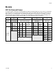
Models Models NXT Air-Powered Pumps Your model number is marked on the pump identification plate located toward the rear of the air motor. To determine the model number of your pump from the following matrix, select the six digits which describe your pump. The first digit is always J for circulation pumps. The remaining five digits define the construction. For example, a circulation pump with carbon steel construction, a 2.
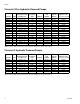
Models Viscount I Plus Hydraulic-Powered Pumps Model No. Series Maximum Pump Working Pressure psi (MPa, bar) 253642 253643 24E787 24E788 253644 253645 253646 253647 253648 253649 253650 253651 253652 253653 253654 253655 A A A A A A A A A A A A A A A A 300 (2.1, 21) 225 (1.6, 16) 300 (2.1, 21) 225 (1.6, 16) 300 (2.1, 21) 225 (1.6, 16) 300 (2.1, 21) 225 (1.6, 16) 300 (2.1, 21) 225 (1.6, 16) 300 (2.1, 21) 225 (1.6, 16) 300 (2.1, 21) 225 (1.6, 16) 300 (2.1, 21) 225 (1.
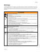
Warnings Warnings The following warnings are for the setup, use, grounding, maintenance, and repair of this equipment. The exclamation point symbol alerts you to a general warning and the hazard symbol refers to procedure-specific risk. Refer back to these warnings. Additional, product-specific warnings may be found throughout the body of this manual where applicable. WARNING FIRE AND EXPLOSION HAZARD Flammable fumes, such as solvent and paint fumes, in work area can ignite or explode.
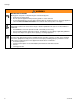
Warnings WARNING MOVING PARTS HAZARD Moving parts can pinch or amputate fingers and other body parts. • Keep clear of moving parts. • Do not operate equipment with protective guards or covers removed. • Pressurized equipment can start without warning. Before checking, moving, or servicing equipment, follow the Pressure Relief Procedure in this manual. Disconnect power or air supply.
Installation Installation Grounding Object being sprayed: follow local code. Solvent pails used when flushing: follow local code. Use only conductive metal pails, placed on a grounded surface. Do not place the pail on a nonconductive surface, such as paper or cardboard, which interrupts grounding continuity. The equipment must be grounded.
Installation Accessories Install the following accessories in the order shown in FIG. 2 and FIG. 3, using adapters as necessary. Hydraulic-Powered Pumps For typical installation, see FIG. 3 on page 11. Hydraulic Power Supply Air-Powered Pumps CAUTION The hydraulic power supply must be kept clean at all to avoid damage to the motor and hydraulic power supply. For typical installation, see FIG. 2 on page 10. Accessory Air Control Kits are available for the NXT Air Motor.
Installation Hydraulic Return Line • • • For Viscount I Plus motors, the hydraulic outlet on the motor is 7/8 in., 37° flare. Use a minimum 5/8 in. (16 mm) ID hydraulic return line (J). For Viscount II motors, use a minimum 22 mm (7/8 in.) ID return line (J). The motor has a 1 in. npt(f) hydraulic oil return fitting. Fluid Line • Fluid filter: with a 60 mesh (250 micron) stainless steel element to filter particles from the fluid as it leaves the pump.
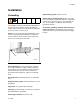
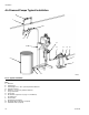
Installation Air-Powered Pumps Typical Installation M J M K L N B D G D E N A F D C TI8398a FIG. 2: Typical Installation Key: A B C D E F G H J K L M N 10 Mix Tank Pump Stand Fluid Supply Line; 1-1/2 in. (38 mm) minimum diameter Fluid Shutoff Valve Fluid Line; 1 in.
Installation Hydraulic-Powered Pumps Typical Installation E L K N P S E R M T J U A D G D B U F D C TI8399a FIG. 3: Typical Installation Key: A B C D E F G J K L M N P R S T Mix Tank Pump Stand Fluid Supply Line; 1-1/2 in. (38 mm) minimum diameter Fluid Shutoff Valve Fluid Line; 1 in. (25 mm) minimum diameter Surge Tank Stand Surge Tank 10 Micron Return Filter Hydraulic Return Line; 5/8 in. (16 mm) minimum diameter Hydraulic Supply Line; 1/2 in.
Operation Operation Pressure Relief Procedure Pump Operation 1. Engage trigger lock. • 2. Air-Powered Pumps only: Close the bleed-type master air valve. Hydraulic-Powered Pumps only: Shut off the hydraulic supply line valve (S) first, then the return line valve (R). 3. Disengage the trigger lock. CAUTION Do not allow the pump to run quickly for a long period of time as this may damage the packings. • In a direct-supply system, the pump starts when the gun is opened, and stops when the gun is closed.
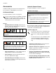
Maintenance Maintenance Preventive Maintenance Schedule The operating conditions of your particular system determine how often maintenance is required. Establish a preventive maintenance schedule by recording when and what kind of maintenance is needed, and then determine a regular schedule for checking your system. Your maintenance schedule should include the following: Excessive Leaking at Throat If you see excessive leaking at the throat, tighten the packing nut (21), see FIG. 4.
Troubleshooting Troubleshooting 1. Relieve the pressure. 2. Check all possible problems and solutions before disassembling pump. PROBLEM Pump output low on both strokes. Pump output low on only one stroke. Pump operates erratically. CAUSE SOLUTION Restricted air or hydraulic supply lines. Clear any obstructions; be sure all shutoff valve are open; increase pressure, but do not exceed maximum working pressure. Exhausted fluid supply. Refill and reprime pump. Clogged fluid outlet line, valves, etc.
Repair Repair • To service the lower, see manual 311690. • To service the air motor, see manual 311238. • To service the Viscount I Plus hydraulic motor, see manual 308330. • To service the Viscount II hydraulic motor, see manual 308048. Disconnect the Lower tie rods. Tighten the locknuts and torque to 50-55 ft-lb (68-75 N•m). 3. Insert the collars (G) into the coupling nut (K). Tighten the coupling nut onto the piston rod (H) and torque to 90-100 ft-lb (122-135 N•m). 4.
Repair 4. Align the lower (D) with the tie rods (C) and loosely install the tie rod locknuts (B). Viscount I Plus Pump Shown E 5. Insert the collars (G) and screw the coupling nut (K) onto the coupling rod (F) and torque to 90-100 ft-lb (122-135 N•m). A 6. For Viscount I Plus pumps, torque the holding the adapter plate (J) to the motor (E) to 15-17 ft-lb (20-23 N•m). For Viscount I Plus and Viscount II pumps, torque the tie rod locknuts (B) to 50-55 ft-lb (68-75 N•m).
Repair 311211M 17
Parts Parts NXT Pumps Common Parts Ref. No. Description 101 MOTOR, NXT, see manual 311238 101 102 103 104 105 106 107 108 Part No. Qty. see table, 1 page 19 LOWER, High-Flo, see manual 311690 see table, 1 page 19 NUT, coupling 184059 1 COLLAR, coupling 184128 2 ADAPTER, coupling 15H369 1 TIE ROD, 14.25 in.
Parts Parts That Vary by Model 101 102 Air-Powered Pump NXT Air Motor High-Flo Lower (see page 3) (see manual 311238) (see manual 311690) JC20L1 N22LN0 253063 JC20M1 N22LT0 253063 JC30L7 N22LN0 253062 JC30M7 N22LT0 253062 JC35L1 N34LN0 253063 JC35M1 N34LT0 253063 JC40L7 N22LN0 253061 JC40M7 N22LT0 253061 JC45L7 N34LN0 253062 JC45M7 N34LT0 253062 JS20L1 N22LN0 253035 JS20L2 N22LN0 253570 JS20L3 N22LN0 253086 JS20L4 N22LN0 253396 JS20L5 N22LN0 253522 JS20L6 N22LN0 253525 JS20M1 N22LT0 253035 JS20M2 N22LT0
Parts 101 102 Air-Powered Pump NXT Air Motor High-Flo Lower (see page 3) (see manual 311238) (see manual 311690) JS45R1 N34RN0 253034 JS45R2 N34RN0 253569 JS45R3 N34RN0 253085 JS45R4 N34RN0 253397 JS45R5 N34RN0 253521 JS45R6 N34RN0 253524 JS45S1 N34RT0 253034 JS45S2 N34RT0 253569 JS45S3 N34RT0 253085 JS45S4 N34RT0 253397 JS45S5 N34RT0 253521 JS45S6 N34RT0 253524 20 311211M
Parts Viscount I Plus Pumps Common Parts 101 111 Ref. No. Description Part No. Qty. 101 MOTOR, Viscount 1+, see manual 261466 1 308330 102 LOWER, High-Flo, see manual 311690 see table, 1 below 103 TIE ROD, 14.25 in.
Parts Viscount II 460 Pumps Common Parts Ref. No. Description Part No. Qty. 101 MOTOR, Viscount II, see manual 223646 1 308048 102 LOWER, High-Flo, see manual 311690 see table, 1 below 103 TIE ROD, 14.25 in.
Dimensions Dimensions Air-Powered Pumps Pump Model NXT cst A in. (mm) 45.60 (1158) B in. (mm) 28.78 (731) Approx. Weight lb (kg) 96 (43) Hydraulic-Powered Pumps Pump Model Viscount I Plus cst Viscount II Approx. A B Weight in. (mm) in. (mm) lb (kg) 49.00 (1245) 28.78 (731) 76 (35) 53.72 (1365) 28.
Pump Mounting Hole Diagram Pump Mounting Hole Diagram Viscount I Plus Models Four 3/8-16 Mounting Holes Gasket 161806 NXT 2200 3.938 in. (100 mm) 9.75 in. (247.7 mm) 6.750 in. (172 mm) Three 5/8-11 Tie Rod Holes 5.906 in. (150 mm) x 120° Bolt Circle TI8071A Four 3/8-16 Mounting Holes Four 0.44 in. (11.1 mm) diameter holes on 10.5 in. bolt circle NXT 3400 Viscount II Models 4X 3/8-16 UNC - 2B 7.43 in. (188 mm) 6.186 in. (157 mm) Six 5/8-11 Tie Rod Holes 6.186 in. (157 mm) 6.186 in. (157 mm) 8.
Technical Data Technical Data NXT Model JX20XX JX30XX JX35XX JX40XX JX45XX Maximum Working Pressure psi (MPa, bar) 200 (1.4, 14) 300 (2.1, 21) 350 (2.4, 24) 400 (2.8, 28) 450 (3.1, 31) Air Operating Range psi (MPa, bar) 100 (0.7, 7.0) Air Consumption See Performance Chart Maximum Fluid Flow at Fluid 60 cycles per Pump Cycles Temperature minute per Gallon Rating gpm (lpm) (Liter) °F (°C) 32 (121) 23 (88) 32 (121) 17 (64) 23 (88) 1.9 (0.5) 2.6 (0.7) 1.9 (0.5) 3.6 (0.9) 2.6 (0.
Performance Charts Performance Charts Air-Powered Pumps Fluid Outlet Pressure - Black Curves Air Consumption - Gray Curves To find Fluid Outlet Pressure (psi/MPa/bar) at a specific fluid flow (gpm/lpm) and operating air pressure (psi/MPa/bar): To find Pump Air Consumption (scfm or m3/min.) at a specific fluid flow (gpm/lpm) and air pressure (psi/MPa/bar): 1. Locate desired flow along bottom of chart. 1. Locate desired flow along bottom of chart. 2.
Performance Charts 2200cc NXT Air Motor, 2000cc High-Flo Lower 3400cc NXT Air Motor, 1500cc High-Flo Lower CYCLES PER MIN. CYCLES PER MIN. 4 8 14 11 17 21 24 0 SCFM (m3/min.) 40 (1.12) 450 (3.1, 31) 30 (0.84) 25 (0.7) B 20 (0.56) A 100 (0.7, 7) 15 (0.42) B 50 (0.3, 3) C 10 (0.28) C 5 (0.14) FLUID PRESSURE 150 (1.0, 10) A AIR FLOW FLUID PRESSURE 35 (0.98) 200 (1.4, 14) 5 10 15 20 24 A 60 (1.68) 350 (2.4, 24) 50 (1.4) B 250 (1.7, 17) 40 (1.12) 200 (1.4, 14) 150 (1.
Performance Charts Hydraulic Powered Pumps Viscount I Plus 225 Pumps Viscount I Plus 300 Pumps 28 311211M
Performance Charts Viscount II 460 Pumps Viscount II 460 - MR4Ball - 2000cc Performance @ 600 1050 1200 PSIG CYCLES PER MIN. 0 4 8 12 16 20 24 28 400 (2.8, 28) 32 36 8 7 A 350 (2.4, 24) 300 (2.1, 21) 6 B 5 250 (1.7, 17) 4 200 (1.4, 14) C 3 OIL FLOW (gpm) FLUID PRESSURE, psi (MPa, bar) 450 (3.1, 31) 150 (1.0, 10) 2 100 (0.7, 7) 1 50 (0.3, 3) 0 (0, 0) 0.0 (0.0) 0 2.0 4.0 6.0 8.0 10.0 12.0 14.0 16.0 18.0 (7.0) (15.0) (22.5) (30.0) (37.9) (45.4) (53.0) (60.6) (68.
Graco Standard Warranty Graco warrants all equipment referenced in this document which is manufactured by Graco and bearing its name to be free from defects in material and workmanship on the date of sale to the original purchaser for use. With the exception of any special, extended, or limited warranty published by Graco, Graco will, for a period of twelve months from the date of sale, repair or replace any part of the equipment determined by Graco to be defective.