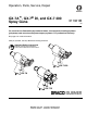
Operation, Parts, Service, Repair GX-7A™, GX-7® DI, and GX-7 400 Spray Guns 311321M EN For use with non-flammable polyurethane foams, two-component coating systems (polyureas), and some two-component epoxy systems. For professional use only. See page 2 for model information. 3500 psi (24 MPa, 240 bar) Maximum Working Pressure Important Safety Instructions Read all warnings and instructions in this manual. Save these instructions.
Models Contents Models . . . . . . . . . . . . . . . . . . . . . . . . . . . . . . . . . . . 2 Warnings . . . . . . . . . . . . . . . . . . . . . . . . . . . . . . . . . 3 Overall View . . . . . . . . . . . . . . . . . . . . . . . . . . . . . . . 6 Centerline Components . . . . . . . . . . . . . . . . . . . 8 Mixing Module . . . . . . . . . . . . . . . . . . . . . . . . . . 10 Operation Basics . . . . . . . . . . . . . . . . . . . . . . . . . . 11 Isocyanate Hazard . . . . . . . . . . . . . . . . . . . . .
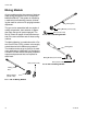
Warnings Warnings The following general warnings are for the setup, use, grounding, maintenance, and repair of this equipment. Additional, more specific warnings may be found throughout the body of this manual where applicable. Symbols appearing in the body of the manual refer to these general warnings. When these symbols appear throughout the manual, refer back to these pages for a description of the specific hazard.
Warnings WARNING FIRE AND EXPLOSION HAZARD Flammable fumes, such as solvent and paint fumes, in work area can ignite or explode. To help prevent fire and explosion: • Use equipment only in well ventilated area. • Eliminate all ignition sources; such as pilot lights, cigarettes, portable electric lamps, and plastic drop cloths (potential static arc). • Keep work area free of debris, including solvent, rags and gasoline.
Warnings WARNING PRESSURIZED ALUMINUM PARTS HAZARD Do not use 1,1,1-trichloroethane, methylene chloride, other halogenated hydrocarbon solvents or fluids containing such solvents in pressurized aluminum equipment. Such use can cause serious chemical reaction and equipment rupture, and result in death, serious injury, and property damage.
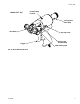
Overall View Overall View Model GX-7A Forward Stop Locknut Valving Rod Rear Stop 2 Air Cap Adjustment Valve ! Gun Block Valving Rod Forward Stop Rear Packing Nut Manual Valves Trigger FIG. 1: GX-7A Overall View Model GX-7 DI FIG.
Overall View Forward Stop Locknut Model GX-7 400 Valving Rod Rear Stop 2 ! Gun Block Air Cap Valve Valving Rod Trigger Forward Stop Rear Packing Nut FIG.
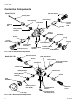
Overall View Centerline Components Model GX-7A A-Screen Screw Valving Rod Check Valve Rear Packing Gun Block Packing Nut Screen Screen Screw Seal Rear Packing Retainer Mixing Module PCD Body Screen O-ring Screen Screw Seal Check Valve Assembly R-Screen Screw Air Cap Front Packing Coupling Block Gasket Pattern Control Disc (PCD) PCD Retainer FIG.
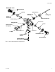
Overall View Model GX-7 400 R-Screen Screw Spring Rear Packing Rear Packing Retainer Valving Rod Screen Screw Seal Rear Seal Retainer Check Valve Check Valve Mixing Module Screen Pattern Control Disc (PCD) Air Cap PCD Retainer Coupling Block Gasket Coupling Block Mounting Screw Gun Block Screen Screw Seal A-Screen Screw FIG.
Overall View Mixing Module All gun models employ the concept of impingement mixing through the use of a single-part MIXING MODULE. This system is cleaned by a mechanical self-cleaning process, eliminating the need for solvent or air purging between dispenses. The gun can be assembled with two styles of mixing components; their selection is dependent upon the type of system sprayed. The Set-Up Charts on pages 44 and 46 show several of the more common sets of these configurations.
Operation Basics Operation Basics Grounding To prevent accidental gun operation, always disconnect air supply before servicing gun or anytime gun is not in use. Isocyanate Hazard Check your local electrical code and proportioner manual for detailed grounding instructions. Ground the spray gun through connection to a Graco-approved grounded fluid supply hose. Spraying materials containing isocyanates creates potentially harmful mists, vapors, and atomized particulates.
Operation Basics Disengage Safety Stop Air Hose Connection To disengage safety stop, push in and turn safety stop counterclockwise to place gun in OPEN position (red band is exposed). Connect Air Hoses Red Band Pull back sleeve of female fitting, insert male fitting and slide sleeve forward to secure connection. Disconnect Air Hoses Pull back sleeve of female fitting and pull out male fitting. OPEN Red band exposed when spraying. Pull Sleeve FIG.
Operation Basics Coupling Block Chemical hoses are joined to gun block by coupling block to ease installation and removal of gun. Manual Valves Two manual valves located on coupling block control flow of each chemical component to gun. Close Manual Valves Use 5/16 in. nut driver to turn manual valve fully clockwise. CAUTION To prevent accidental gun operation, always set safety stop to CLOSED (SERVICE), close both manual valves, and disconnect air supply.
Operation Basics 3. Insert coupling block mounting screw and use 5/16 in. nut driver to tighten to gun block. Optional Configuration Refer to page 42. If bottom-mount hose connection is desired, alternate swivel fitting (2 and 3) with pipe plugs (1). Use pipe thread sealant. Do not cross-over which side each fitting is on. Air Inlet Configuration Coupling Block Gaskets There are two configurations for the air inlet.
Operation Basics Mixing Module and PCD Installation f. Use wrench to loosen piston locknut. Turn valving rod rearward as far as it will turn. 1. Install mixing module: a. Disconnect gun from coupling block. b. Connect air supply to gun. g. Place and orient PCD over mixing module retainer. h. Install PCD retainer and hand tighten (GX-7 DI model only). c. Set safety stop to OPEN. d. Hold down trigger and place module over tip of valving rod. e.
Operation Basics Valving Rod Adjustment GX-7A and GX-7 400 Models Only 1. Push in rear stop to SERVICE position. 2. If attached, turn both manual valves fully clockwise to close (see Manual Valves, page 13). 3. Connect air line from gun to air source to pressurize air cylinder forward to CLOSED position. FIG. 18: One Wrench Flat 4. Loosen forward stop locknut.
Operation Basics Initial Set Up 5. Bleed air from chemical hoses. 1. Install female quick disconnect fitting to air supply hose bundled with chemical supply hoses. 2. Connect coupling block to hose bundle. Connect A-Isocyanate hose (red-tape) to notched fitting on coupling block. Connect R-Resin hose (blue-tape) to fitting without notches on coupling block. 3. Close both manual valves. 4. Pressurize A and R chemical hoses. Check for leaks. See Proportioner manual. a.
Operation Basics Daily Start-up Ensure gun is attached to coupling block and air hose. Ensure proportioning unit is at desired temperature and pressure. Properly ground equipment to avoid static sparking that may result in fire or explosion. 1. Connect air supply to gun. 2. Adjust air cap adjustment valve. Turn knob counterclockwise to open valve and clockwise to close valve 3. Adjust rear seal retainer. 4. Open both manual valves. See Coupling Block section, page 13. 5. Set safety stop to OPEN. 6.
Pressure Relief Procedure Pressure Relief Procedure 4. Release gun trigger, set safety stop to CLOSED, and close manual valves. Relieve pressure before cleaning or repairing gun. 1. Close both manual valves. If fluid in hose and proportioner is still under pressure, follow Pressure Relief Procedure in proportioner manual To relieve pressure in hose after gun is removed, place fluid manifold over containers, facing away from you. Very carefully open fluid valves.
Maintenance Maintenance Use supplied tool kit 296835. See Tool Kit, page 48. Gun Service Kits Use either the 1-Quart Gun Service Kit (296980) or 3-Gallon Gun Service Kit (296981) to perform daily flushing of spray gun without disassembly. FIG. 23: 3-Gallon Gun Service Kit For more information about the 3-Gallon Gun Service Kit, see Manual 311341. Clean Spray Gun Procedure FIG. 22: 1-Quart Gun Service Kit For more information about the 1-Quart Gun Service Kit, see Manual 311340.
Maintenance 3. Remove gun from coupling block. 4. Attach service block of gun service kit to spray gun, and then tighten using 5/16 in. nut driver. 5. Pressurize Service Kit container up to 100 psi. DO NOT EXCEED 100 psi (0.7 MPa, 7 bar). 6. Open one manual valve on service block. Flush Gun To avoid static sparking that may result in fire or explosion, ensure all equipment in flushing procedure is grounded. Do not flush on or near foamed or coated surfaces. 1. Set safety stop to CLOSED (SERVICE). 7.
Repair Repair Remove Centerline Components Shutdown proportioner and allow chemicals to cool before servicing gun. Refer to FIG. 4 through FIG. 6 for diagrams of centerline components for all gun models. Clean A and R components in separate containers to avoid cross contamination. 1. Flush gun according to Clean Spray Gun Procedure, page 20. Service Screen Screw 2. Connect air supply to gun. Set safety stop to OPEN. 1. Flush gun according to Clean Spray Gun Procedure, page 20. 3. Remove air cap. 2.
Repair of mixed material from rod using cloth soaked in gun cleaner or fine steel wool. 11. Remove valving rod. Rod Draw Bar If valving rod is replaced, it is recommended to reset forward stop. Valving Rod Rear Stop FIG. 24: Remove Valving Rod (GX-7 DI model) 13. Disconnect air supply. 14. Remove gun block retaining screw. Carefully slide gun block away from air cylinder. If dried chemical is built up on gun block, remove dried chemical before you remove gun block. 15. Clean all components thoroughly.
Repair Install Centerline Components 11. Install PCD over end of mixing module retainer. GX-7 DI Model Only 12. Thread PCD retainer onto gun block. Hand tight. Before installation, ensure all gun components are clean and dry. Lubricate all moving parts and threads. 13. Rotate flat PCD to adjust orientation as required. 1. Install rear packing gland with packing wrench. Tighten onto gun block. 14. Adjust valving rod. See Valving Rod Adjustment, page 16. 15. Thread air cap into place; hand tight. 2.
Repair Replace End Cap and Air Piston Assembly 10. By hand, pull piston assembly out of air cylinder and inspect o-ring for damage. Replace if necessary. Apply Lubriplate grease prior to installation. End Cap Spacer Piston Assembly Front U-Cup Seal Piston Spring ensure “cup” faces front of air cylinder when replacing. Rear U-Cup Seal Socket Head Cap Screw Cylinder Clamp GX-7 DI Shown FIG. 26: GX-7 DI End Cap and Air Piston Assembly 1. Clean gun according to Clean Spray Gun Procedure, page 20. 11.
Repair Replace Trigger Valve O-Rings 8. Remove rear internal pipe plug (under pipe plug). 1. Clean gun according to Clean Spray Gun Procedure, page 20. 9. Use pin punch and hammer to gently tap spring seat until it and valve liner push out opposite end of hole. 2. Disconnect air supply from gun. Refer to Parts, page 30. 10. Remove 4 o-rings on liner. 11. Apply thick coat of Lubriplate grease to new o-rings and install. 12. Clean valve hole. Remove any dirt and debris.
Repair Clean Mixing Module 1. Flush gun according to Clean Spray Gun Procedure, page 20. 2. Connect air supply to gun. Set safety stop to OPEN. 3. Remove air cap by hand. GX-7A and GX-7 400 Models Only Air cap and PCD retainer may be difficult to separate during disassembly due to overtightening or hardened mixed material. Fit the side of the stamped 5/8 in. wrench into the groove to separate. When reinstalling, apply lubricant to threads. 8. Set safety stop to OPEN.
Repair Install Mixing Module 1. Install safety stop; leave in OPEN position. 11. Slide safety stop onto rear of air cylinder. Push safety stop partially forward and rotate clockwise to set to OPEN. 2. Connect air supply to gun. 3. Depress gun trigger and slide mixing module over end of valving rod. GX-7 DI model only: ensure valving rod alignment pin enters alignment slot in gun block. Keep gun trigger depressed. 4.
Repair Clean Pattern Control Disc 1. Set safety stop to CLOSED (SERVICE). 2. Close both manual valves. 3. Turn off air to air cap. 4. Use cotton swab soaked in gun cleaner to clean external surface of material build up. Light scrubbing with impinger cleanout brush may also be required. a. Trigger gun to SERVICE position and clean orifice area. It is not always possible to clean all material build-up from PCD while assembled to gun. In this case, remove PCD and clean inside radius of disc.
Parts Parts GX-7A Model Final Assembly Part Numbers 295542, 295543, 295544, 295545 1 6 7 25 8 22 9 5 24 12 11 R 9 A 13 23 8 7 16 10 14 15 21 20 18 17 2, 26 19 4 3 30 311321M
Parts GX-7A Model Final Assembly Part Numbers 295542, 295543, 295544, 295545 Ref. No. 1 2 3 4 5 6 7 8 9 Part No. 295810 15B772 295596 295597 296834 296693 296723 296792 296724 296722 10 11 295384 12 13 14 15 16 17 18 19 296976 20 296833 21 22 23 296828 296829 24 25 26 296830 16K136 100030 296978 295868 296832 296831 296128 295433 296979 311321M Description Qty.
Parts GX-7 DI Model Final Assembly (295541) 5 1 19 8 6 7 9 18 17 10 11 12 7 6 13 14 16 15 3 4 2, 21 32 311321M
Parts GX-7 DI Model Final Assembly (295541) Ref. No. 1 2 3 4 5 6 7 Part No. 295809 15B772 295596 295597 295835 296792 296724 296713 8 9 295860 10 11 12 13 14 295837 296865 295838 296128 15 295433 296979 16 17 18 19 20 21 295834 295836 296864 296829 295383 100030 311321M Description Qty. Spray gun handle assembly 1 Air hose, 1/4 in. x 23 in.
Parts GX-7 400 Model Final Assembly (295540) 7 11 12 8 9 14 6 16 18 23 R 6 A 21 15 9 20 12 10 5 19 22 2 1, 24 13 4 3 34 311321M
Parts GX-7 400 Model Final Assembly (295540) Ref. No. Part No. Description Qty.
Parts GX-7A Model Handle Assembly (24K734) 6 3 2 8 27 7 18 9 12 14 37 15 4 27 10 36 32 17 11 16 42 28 39 19 41 43 34 24 26 38 40 28 35 1 23 30 13 27 21 33 36 5 20 311321M
Parts GX-7 Model Handle Assembly (24K734) Ref. No. 1 2 3 4 5 Part No. 296862 295678 295676 295675 295709 6 7† 8◆ 9† 10 11† 12 13 14 15† 16 17 18 19 295680 295681 16K136 295683 295663 514279 295664 295665 295666 295667 295673 295677 295668 295669 20 295671 21 295688 23 295686 24 295689 26❄ 296971 27†❄106555 28†❄C20988 30 295438 32† 295405 33 295692 34 295684 35 36† 37† 38 295687 295674 295706 295693 39 295662 40 103656 41 42 295690 C20003 43† 295685 311321M Description Qty.
Parts GX-7 DI Model Handle Assembly (295809) 25 10 9 18 12 2 17 34 11 19 13 20 14 3 40 15 34 22 29 16 31 30 7 24 37 27 8 33 38 36 39 30 5 1 4 32 21 28 6 35 38 26 23 311321M
Parts GX-7 DI Model Handle Assembly (295809) Ref. No. 1 2 3 4 5 6 7 8 9 10 11 12 13 14 15 16 17 18 19† 20† 21 22 Part No. 296862 295714 295715 295686 295687 295688 295689 295690 295716 295717 295718 296736 295720 295712 295721 295713 296863 295676 295681 295683 295665 295669 23 24 25 295671 295431 295722 26 295709 27 295662 28❄ 106555 29† C20988 30†❄103337 31 295684 32 33† 34† 35 36 295438 295685 295496 295692 295693 37 C20003 38❄ 295442 39 103656 40† 103338 Description Qty.
Parts GX-7 400 Model Handle Assembly (24K733) 15 14 32 17 3 16 25 18 23 21 39 24 40 30 3 19 8 20 29 28 31 11 4 2 26 33 7 5 37 AX SI M 5P 12 12 10 4 35 38 34 6 13 22 3 36 9 40 1 27 311321M
Parts GX-7 400 Model Handle Assembly (24K733) Ref. No. 1 2 3†❄ 4†❄ 5 6 7†❄ 8† 9 10 11 12❄ 13 14 15 16† 17◆ 18† 19 20† 21 22 23 24† 25 26 Part No.
Parts Coupling Block Assembly (295383) All models 5 1 1 2 6 4 3 Ref. No. 1 2 3 4 Part No. 295662 117634 117635 295693 5 6 296970 296215 42 Description Pipe plug, flush seal, 1/8 in. R-swivel fitting A-swivel fitting Pipe plug, flush seal, 1/16 in. Manual valve assembly Coupling block Qty .
Specifications Specifications GX-7A Mix Module Kit Module Kit†❄ Module Only Cleanout Tool Part No. Size Ref. Part No. Size Ref. (A) Iso Port Part No. Diameter in/(mm) (R) Resin Port Part No. Diameter in/(mm) 296909 #1 Round 296907 #1 Round 246807 .0320 (.81) 246807 .032 (.81) 296916 #2 Round 296225 #2 Round 246816 .018 (.45) 246816 .018 (.45) 296919 #3 Round 296226 #3 Round 276984 .0225 (.57) 246816 .018 (.45) 296921 #4 Round n/a #4 Round 296290 .035 (.89) 246807 .
Specifications Set-Up Chart for GX-7A Model Pressure (psi) Output (lbs/min) Pattern Dia. (inches) Module Part No. Polyol Port Size No. Orifices Iso Port Size No. Orifices Tip Round Spray Pattern 1000 22 ❄22 296909 (#1) .0320 4 .0320 4 296712 1000 12 ❄12 296919 (#3) .0180 4 .0225 4 296710 1600 16 ❄14 296923 (#5) .0280 4 .0225 4 296710 2000 30 ❄24 296909 (#1) .0320 4 .0320 4 296694 3000 40 ❄24 296921 (#4) .0320 4 .0350 4 296695 Pour Pattern 600 3.
Specifications GX-7 400 Mix Module Kit Module Kits Cleanout Drill Iso Port Part No. Diameter in/(mm) Polyol Port Part No. Diameter in/(mm) 1 12 246816 .018 (.45) 246816 .018 (.45) 451 Fan 1 12 246816 .018 (.45) 246816 .018 (.45) 296888 296887 452 Fan 1 12 246631 .020 (.51) 246631 .020 (.51) 296891 296890 453 Fan 1 12 296287 .025 (.64) 276984 .0225 (.57) Part No. Size Ref. Quantity 296885 296884 402 Round 296859 296860 CAUTION Each module kit includes cleanout drills.
Specifications Set-up Chart for GX-7 400 Model Pressure (psi) Output (lbs/min) Pattern Dia. (inches) Module Part No. Polyol Port Size No. Orifices Iso Port Size No. Orifices Tip 1 .0180 1 296858 Round Spray Pattern 1500 3.5 ✖8 296885 (402) .0180 Fan Spray Pattern 1500 3.5 ❖16 x 3 296859 (451) .0180 1 .0180 1 296853 1500 4.5 ❖16 x 3 296888 (452) .0200 1 .0200 1 296853 1500 8.0 ❖16 x 3 296891 (453) .0225 2 .0250 2 296855 ✖ At 24 in. above substrate ❖At 18 in.
Specifications GX-7 DI Model Specifications Module/Tip Data for Chemical Sprayed at 2500 PSI ✖ Module Kit Cleanout Drill Ref. No. ❄Pattern ❄Output (lbs/min) Fan Spray Pattern 296900 (#2) 246625 212 12 in. wide 12 (.086 diameter) 206 20 in. wide 22 213 12 in. wide 12 204 20 in. wide 21 248892 212 10 in. wide 8 (.028 diameter) 206 24 in. wide 11 204 18 in. wide 10 246816 212 11 in. wide 4 (.018 diameter) 213 12 in. wide 4 208 8 in.
Specifications Tip Kits For GX-7A and GX-7 DI Models Round Tip Kits Flat Tip Kits Part No. No. Ref. Qty. 296698 202 1 296699 203 1 Part No. Size Qty. 296708 40 1 296709 46 1 296700 204 1 296717 55 5 296701 206 1 296710 70 1 296702 208 1 1 70 5 296703 209 296718 296711 80 1 296704 210 1 296719 80 5 296715 210 5 90 1 296882 212.
Technical Data Technical Data Category Air Supply Maximum Operating Pressure Maximum Output ❄ Minimum Output ❄ Height Length Width Weight Mixing Data 100-125 psi (0.7-0.9 MPa, 6.9-8.6 bar) 3500 psi (24 MPa, 240 bar) GX-7A Model: 40 lbs/min (18 kg/min) GX-7 DI Model: 22 lbs/min (10 kg/min) GX-7 400 Model: 8 lbs/min (3.6 kg/min) GX-7A Model: 4 lbs/min (1.8 kg/min) GX-7 DI Model: 4 lbs/min (1.8 kg/min) GX-7 400 Model: 3.5 lbs/min (1.6 kg/min) 9 in. (23 cm) 9.5 in. (24 cm) 4.5 in. (11 cm) 3.5 lbs. (1.
Graco Standard Warranty Graco warrants all equipment referenced in this document which is manufactured by Graco and bearing its name to be free from defects in material and workmanship on the date of sale to the original purchaser for use. With the exception of any special, extended, or limited warranty published by Graco, Graco will, for a period of twelve months from the date of sale, repair or replace any part of the equipment determined by Graco to be defective.