Instructions - Parts List 4-Ball Lower Retrofit Connection Kits 311876F EN Connection kits for 4-Ball Lowers. For professional use only. Important Safety Instructions Read all warnings and instructions in your pump Operation manual. Save these instructions. See the Connection Kit Usage Charts on pages 2-5 to select the correct connection kit for your lower and motor. A Shield Kit may also be required. See manual 406876 to order the correct shield kit for your pump.
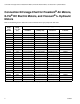
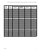
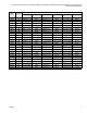
Connection Kit Usage Chart for President® Air Motors, E-Flo® DC Electric Motors, and Viscount® I+ Hydraulic Motors Connection Kit Usage Chart for President® Air Motors, E-Flo® DC Electric Motors, and Viscount® I+ Hydraulic Motors Refer to the following chart to select the correct Connection Kit for your pump lower and motor. * 2 Connection Kit Part No. (see page numbers) Pump Lower Part No.
Connection Kit Usage Chart for President® Air Motors, E-Flo® DC Electric Motors, and Viscount® I+ Hydraulic Motors Connection Kit Part No. (see page numbers) Pump Lower Part No.
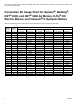
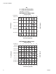
Connection Kit Usage Chart for Senator®, Bulldog®, NXT® 2200, and NXT® 3400 Air Motors, E-Flo® DC Electric Motors, and Viscount® II Hydraulic Motors Connection Kit Usage Chart for Senator®, Bulldog®, NXT® 2200, and NXT® 3400 Air Motors, E-Flo® DC Electric Motors, and Viscount® II Hydraulic Motors Refer to the following chart to select the correct Connection Kit for your pump lower and motor. 4 Connection Kit Part No. (see page numbers) Pump Lower Part No.
Connection Kit Usage Chart for Senator®, Bulldog®, NXT® 2200, and NXT® 3400 Air Motors, E-Flo® DC Electric Motors, and Viscount® II Hydraulic Motors Connection Kit Part No. (see page numbers) Pump Lower Part No.
Connection Kit 288202 Connection Kit 288202 Connects Old Style 4-Ball Lower to NXT 2200 or NXT 3400 Air Motor, or E-Flo DC Electric Motor NOTE: See the Connection Kit Usage Chart on page 4 to find the lowers and motors which use Connection Kit 288202. Parts List and Drawing Ref. Part. 1 2 3 5 7 14 Description 15G924 108683 111368 15H980 100103 108284 Qty 3 3 1 1 1 1 ROD, tie NUT, lock, hex SEALANT; 0.
Connection Kit 288202 Pump Performance Charts NOTE: See pages 10-12 for E-Flo DC Performance Charts. Air Consumption To find air consumption (l/min. or gpm) at a specific fluid flow (l/min. or gpm) and operating pressure (A/B/C): Fluid Outlet Pressure To find fluid outlet pressure (MPa/bar/psi) at a specific flow (lpm/gpm) and operating pressure (A/B/C): 1. Locate desired flow at bottom of chart. 2. Follow vertical line up to intersection with selected operating pressure curve (solid line).
Connection Kit 288202 Key A 0.7 MPa, 7 bar (100 psi) air pressure B 0.5 MPa, 4.9 bar (70 psi) air pressure C 0.3 MPa, 2.8 bar (40 psi) air pressure Test Fluid: No. 10 Weight Oil NXT 2200 with 1500cc Lower cycles per minute psi (MPa, bar) 5 10 15 21 26 31 36 300 (2.0, 20) 50 A A 45 40 35 B 200 (1.3, 13) B 30 25 150 (1.0, 10) 20 C 100 (0.68, 6.8) Air Flow (scfm) Fluid Pressure 250 (1.7, 17) 15 C 10 50 (0.34, 3.4) 5 0 2.0 (7.5) 12.0 6.0 8.0 10.0 4.0 (15.1) (22.7) (30.2) (37.8) (45.
Connection Kit 288209 Connection Kit 288209 Connects 4-Ball Lower with Torqueable or Spring Loaded Throat Packings to NXT 2200 or NXT 3400 Air Motor, or E-Flo DC Electric Motor NOTE: See the Connection Kit Usage Charts on pages 2-5 to find the lowers and motors which use Connection Kit 288209. Parts List and Drawing Ref. Part. 1 2 3 5 7 8 Description 15G924 108683 111368 15H369 184128 184059 Qty 3 3 1 1 2 1 ROD, tie NUT, lock, hex SEALANT; 0.
Connection Kit 288209 Pump Performance Charts NOTE: See pages 7-8 for NXT 2200 and NXT 3400 Performance Charts. Fluid Outlet Pressure To find fluid outlet pressure (psi/MPa/bar) at a specific flow (gpm/lpm) and percentage of maximum force (A/B/C): 1. Locate desired flow at bottom of chart. 2. Follow vertical line up to intersection with selected percentage of maximum force (see the Key below). 3. Follow left to vertical scale to read fluid outlet pressure.
Connection Kit 288209 1 HP Motor (1400 lb maximum force) with 1000cc Lower cycles per minute Fluid Pressure psi (MPa, bar) A B C Fluid Flow in gpm (lpm) 2 HP Motor (2800 lb maximum force) with 1000cc Lower cycles per minute psi (MPa, bar) Fluid Pressure A B C Fluid Flow in gpm (lpm) 311876F 11
Connection Kit 288209 2 HP Motor (2800 lb maximum force) with 1500cc Lower cycles per minute psi (MPa, bar) Fluid Pressure A B C Fluid Flow in gpm (lpm) 2 HP Motor (2800 lb maximum force) with 2000cc Lower cycles per minute Fluid Pressure psi (MPa, bar) A B C Fluid Flow in gpm (lpm) 12 311876F
Connection Kit 288208 Connection Kit 288208 Connects 4-Ball Lower with Torqueable Throat Packings to Bulldog or Senator Air Motor NOTE: See the Connection Kit Usage Chart on page 5 to find the lowers and motors which use Connection Kit 288208. Parts List and Drawing Ref. 1 2 3 5 8 10 Part.
Connection Kit 288208 Pump Performance Charts Fluid Outlet Pressure Air Consumption To find fluid outlet pressure (MPa/bar/psi) at a specific flow (lpm/gpm) and operating pressure (A/B/C): To find air consumption (l/min. or gpm) at a specific fluid flow (l/min. or gpm) and operating pressure (A/B/C): 1. Locate desired flow at bottom of chart. 1. Locate desired flow along bottom of chart. 2. Follow vertical line up to intersection with selected operating pressure curve (solid line).
Connection Kit 288208 Key A 0.7 MPa, 7 bar (100 psi) air pressure B 0.5 MPa, 4.9 bar (70 psi) air pressure C 0.3 MPa, 2.8 bar (40 psi) air pressure Test Fluid: No. 10 Weight Oil Senator with 1500cc Lower cycles per minute psi (MPa, bar) 300 (2.0, 20) 250 (1.7, 17) 5 10 15 21 26 31 36 45 A A 40 35 Fluid Pressure B B 30 25 150 (1.0, 10 20 C 100 (0.69, 6.9) C Air Flow (scfm) 200 (1.3, 13) 15 10 50 (0.34, 3.4) 5 0 2.0 (7.5) 6.0 8.0 4.0 (15.1) (22.7) (30.2) 12.0 10.0 (37.8) (45.4) 14.
Connection Kit 288208 Key A 0.7 MPa, 7 bar (100 psi) air pressure B 0.5 MPa, 4.9 bar (70 psi) air pressure C 0.3 MPa, 2.8 bar (40 psi) air pressure Test Fluid: No. 10 Weight Oil Bulldog with 1500cc Lower cycles per minute 5 psi (MPa, bar) 10 15 21 26 31 36 70 450 (3.1, 31) A 400 (2.7, 27) A 60 350 (2.4, 24) Fluid Pressure B B 40 250 (1.7, 17) 200 (1.3, 13) C C 150 (1.0, 10 30 Air Flow (scfm) 50 300 (2.0, 20) 20 100 (0.69, 6.9) 10 50 (0.34, 3.4) 0 2.0 (7.5) 12.0 6.0 8.0 10.0 4.
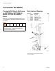
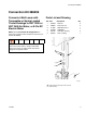
Connection Kit 288504 Connection Kit 288504 Connects 4-Ball Lower with Torqueable Throat Packings to President Air Motor NOTE: See the Connection Kit Usage Chart on page 3 to find the lowers and motors which use Connection Kit 288504. Parts List and Drawing Ref. Part. 3 5 7 8 184128 15J948 100579 184059 Description Qty 2 1 1 1 COLLAR, coupling ADAPTER PIN, cotter NUT, coupling 7 5 2 3 8 1 TI8986a 311876F 1 Torque to 145-150 ft-lb (197-203 N•m). 2 Apply lubricant.
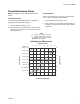
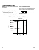
Connection Kit 288504 Pump Performance Charts Fluid Outlet Pressure To find fluid outlet pressure (MPa/bar/psi) at a specific flow (lpm/gpm) and operating pressure (A/B/C/D): Air Consumption To find air consumption (l/min. or gpm) at a specific fluid flow (l/min. or gpm) and operating pressure (A/B/C/D): 1. Locate desired flow at bottom of chart. 2. Follow vertical line up to intersection with selected operating pressure curve (solid line). Follow left to scale to read fluid outlet pressure. 1.
Connection Kit 288504 Key A 1.17 MPa, 11.7 bar (170 psi) air pressure B 0.7 MPa, 7 bar (100 psi) air pressure C 0.5 MPa, 4.9 bar (70 psi) air pressure D 0.3 MPa, 2.8 bar (40 psi) air pressure Test Fluid: No. 10 Weight Oil President with 1500cc Lower cycles per minute psi (MPa, bar) 300 (2.0, 20) 6 12 18 25 30 37 43 A A 45 40 250 (1.7, 17) 35 Fluid Pressure 150 (1.0, 10) B 25 B 20 100 (0.69, 6.9) C C Air Flow (scfm) 30 200 (1.3, 13) 15 D 10 D 50 (0.34, 3.4) 5 0 2.0 (7.5) 6.0 8.
Connection Kit 24F308 Connection Kit 24F308 Connects 4-Ball Lower with Spring Loaded Throat Packings to Bulldog or Senator Air Motor NOTE: See the Connection Kit Usage Chart on pages 4-5 to find the lowers and motors which use Connection Kit 24F308. Parts List and Drawing Ref. 1 2 3 4 5 6 Part.
Connection Kit 24F308 Pump Performance Charts Fluid Outlet Pressure Air Consumption To find fluid outlet pressure (MPa/bar/psi) at a specific flow (lpm/gpm) and operating pressure (A/B/C): To find air consumption (l/min. or gpm) at a specific fluid flow (l/min. or gpm) and operating pressure (A/B/C): 1. Locate desired flow at bottom of chart. 1. Locate desired flow along bottom of chart. 2. Follow vertical line up to intersection with selected operating pressure curve (solid line).
Connection Kit 24F308 Key A 0.7 MPa, 7 bar (100 psi) air pressure B 0.5 MPa, 4.9 bar (70 psi) air pressure C 0.3 MPa, 2.8 bar (40 psi) air pressure Test Fluid: No. 10 Weight Oil Senator with 1500cc Lower cycles per minute psi (MPa, bar) 300 (2.0, 20) 250 (1.7, 17) 5 10 15 21 26 31 36 45 A A 40 35 Fluid Pressure B B 30 25 150 (1.0, 10 20 C 100 (0.69, 6.9) C Air Flow (scfm) 200 (1.3, 13) 15 10 50 (0.34, 3.4) 5 0 2.0 (7.5) 6.0 8.0 4.0 (15.1) (22.7) (30.2) 12.0 10.0 (37.8) (45.4) 14.
Connection Kit 24F308 Key A 0.7 MPa, 7 bar (100 psi) air pressure B 0.5 MPa, 4.9 bar (70 psi) air pressure C 0.3 MPa, 2.8 bar (40 psi) air pressure Test Fluid: No. 10 Weight Oil Bulldog with 1500cc Lower cycles per minute psi (MPa, bar) 5 10 15 21 26 31 36 70 450 (3.1, 31) A 400 (2.7, 27) A 60 350 (2.4, 24) Fluid Pressure B B 40 250 (1.7, 17) 200 (1.3, 13) C C 150 (1.0, 10 30 Air Flow (scfm) 50 300 (2.0, 20) 20 100 (0.69, 6.9) 10 50 (0.34, 3.4) 0 2.0 (7.5) 12.0 6.0 8.0 10.0 4.
Connection Kits 24J185 (shown) and 24J186 Connection Kits 24J185 (shown) and 24J186 Connects 4-Ball Lower with Spring Loaded Throat Packings to President Air Motor NOTE: See the Connection Kit Usage Chart on pages 2-3 to find the lowers and motors which use Connection Kits 24J185 and 24J186. Parts List and Drawing Ref. Part.
Connection Kits 24J185 (shown) and 24J186 Pump Performance Charts Fluid Outlet Pressure Air Consumption To find fluid outlet pressure (MPa/bar/psi) at a specific flow (lpm/gpm) and operating pressure (A/B/C): To find air consumption (l/min. or gpm) at a specific fluid flow (l/min. or gpm) and operating pressure (A/B/C): 1. Locate desired flow at bottom of chart. 1. Locate desired flow along bottom of chart. 2.
Connection Kits 24J185 (shown) and 24J186 Key A 0.7 MPa, 7 bar (100 psi) air pressure B 0.5 MPa, 4.9 bar (70 psi) air pressure C 0.3 MPa, 2.8 bar (40 psi) air pressure Test Fluid: No. 10 Weight Oil President with 1000cc Lower 8 400 (2.7, 27) 17 25 33 42 51 59 68 300 (2.0, 20) 200 (1.3, 13) A B 100 (0.69, 6.9) C 2.0 4.0 6.0 8.0 10.0 12.0 14.0 16.0 (7.5) (15.1) (22.7) (30.2) (37.8) (45.4) (53.0) (60.8) 0 cycles per minute (m3/min) 50 (1.
Connection Kit 24F065 Connection Kit 24F065 Connects 4-Ball Lower with Spring Loaded Throat Packings to Viscount I+ Hydraulic Motor NOTE: See the Connection Kit Usage Chart on pages 2-3 to find the lowers and motors which use Connection Kit 24F065. Parts List and Drawing Ref. Part.
Connection Kit 24F065 Pump Performance Charts Fluid Outlet Pressure Hydraulic Oil Consumption To find fluid outlet pressure (psi/MPa/bar) at a specific fluid flow (lpm/gpm) and operating hydraulic pressure (psi/MPa/bar): To find motor hydraulic oil consumption (l/min. or gpm) at a specific fluid flow (l/min. or gpm): 1. Locate desired flow along bottom of chart. 2. Follow vertical line up to intersection with selected fluid outlet pressure curve (black).
Connection Kit 24F065 Viscount I+ Motor, 1500cc Lower Viscount I+ Motor, 2000cc Lower CPM psi (MPa, bar) 12 24 GPM 36 48 PUMP OUTLET PRESSURE A 2.5 (9.5) 120 0.84, 8.4) 80 (0.56, 5.6) 40 (0.28, 2.8) 2.0 (7.6) B 1.5 (5.7) 1.0 (3.8) C 0.5 (1.9) HYDRAULIC OIL CONSUMPTION 160 (1.12, 11.2) 60 (l/min) 3.0 (11.4) 0 GPM 0 (l/min) 5 (19) 10 (38) 15 (57) 20 (76) 25 (95) PUMP DELIVERY (Test Fluid: No.
Connection Kit 24J390 Connection Kit 24J390 Connects 4-Ball Lower with Spring Loaded Throat Packings to Viscount II Hydraulic Motor NOTE: See the Connection Kit Usage Chart on pages 4-5 to find the lowers and motors which use Connection Kit 24J390. Parts List and Drawing Ref. Part.
Connection Kit 24J390 Pump Performance Charts Fluid Outlet Pressure Hydraulic Oil Consumption To find fluid outlet pressure (psi/MPa/bar) at a specific fluid flow (lpm/gpm) and operating hydraulic pressure (psi/MPa/bar): To find motor hydraulic oil consumption (l/min. or gpm) at a specific fluid flow (l/min. or gpm): 1. Locate desired flow along bottom of chart. 2. Follow vertical line up to intersection with selected fluid outlet pressure curve (black).
Graco Information For the latest information about Graco products, visit www.graco.com. For patent information, see www.graco.com/patents. TO PLACE AN ORDER, contact your Graco distributor or call to identify the nearest distributor. Phone: 612-623-6921 or Toll Free: 1-800-328-0211 Fax: 612-378-3505 All written and visual data contained in this document reflects the latest product information available at the time of publication. Graco reserves the right to make changes at any time without notice.