Operation 312065M EN Electric, Heated, Plural Component Proportioner For spraying polyurethane foam and polyurea coatings. For professional use only. Not approved for use in European explosive atmosphere locations. Important Safety Instructions Read all warnings and instructions in this manual. Save these instructions. See page 4 for model information, including maximum working pressure and approvals.
Contents Systems . . . . . . . . . . . . . . . . . . . . . . . . . . . . . . . . . . 3 Models . . . . . . . . . . . . . . . . . . . . . . . . . . . . . . . . . . . 4 Supplied Manuals . . . . . . . . . . . . . . . . . . . . . . . . . . 5 Related Manuals . . . . . . . . . . . . . . . . . . . . . . . . . . . 5 Warnings . . . . . . . . . . . . . . . . . . . . . . . . . . . . . . . . . 7 Important Two-Component Material Information 10 Isocyanate Conditions . . . . . . . . . . . . . . . . . . . .
Systems Systems Part Maximum Fluid Working Pressure psi (MPa, bar) Heated Hose Gun Proportioner (see page 4) 50 ft (15 m) 10 ft (3 m) Model Part Mix Chamber Kit AP9024 2500 (17.2, 172) 259024 246679 246055 Fusion™ Air Purge 246100 AR2020 AP9025 2000 (13.8, 138) 259025 246678 246050 Fusion™ Air Purge 246101 AR5252 AP9026 2000 (13.8, 138) 259026 246678 246050 Fusion™ Air Purge 246101 AR5252 AP9028 3500 (24.
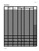
Models Models E-20 SERIES Part, Series Full Load Peak Voltage Amps* (phase) 259025, E 259030, E 259034, E 48 24 32 230V (1) 400V (3) 230V (3) System Watts† Primary Heater Watts Max Flow Rate lb/min (kg/min) Approximate Output per Cycle Maximum Fluid (A+B) Working Pressure gal. (liter) psi (MPa, bar) 10,200 10,200 10,200 6,000 6,000 6,000 20 (9) 20 (9) 20 (9) 0.0104 (0.0395) 0.0104 (0.0395) 0.0104 (0.
Supplied Manuals Supplied Manuals Related Manuals The following manuals are shipped with the Reactor™ Proportioner. Refer to these manuals for detailed equipment information. The following manuals are for accessories used with the Reactor™. Order Part 15M334 for a compact disk of Reactor manuals translated in several languages. Manuals are also available at www.graco.com. Order Part 15M334 for a compact disk of Reactor manuals translated in several languages.
Related Manuals 6 312065M
Warnings Warnings The following warnings are for the setup, use, grounding, maintenance, and repair of this equipment. The exclamation point symbol alerts you to a general warning and the hazard symbol refers to procedure-specific risk. Refer back to these warnings. Additional, product-specific warnings may be found throughout the body of this manual where applicable. WARNING ELECTRIC SHOCK HAZARD This equipment must be grounded. Improper grounding, setup, or usage of the system can cause electric shock.
Warnings WARNING FIRE AND EXPLOSION HAZARD Flammable fumes, such as solvent and paint fumes, in work area can ignite or explode. To help prevent fire and explosion: • • • • • • • • • Use equipment only in well ventilated area. Eliminate all ignition sources; such as pilot lights, cigarettes, portable electric lamps, and plastic drop cloths (potential static arc). Keep work area free of debris, including solvent, rags and gasoline.
Warnings WARNING EQUIPMENT MISUSE HAZARD Misuse can cause death or serious injury. • This equipment is for professional use only. • Do not leave the work area while equipment is energized or under pressure. Turn off all equipment and follow the Pressure Relief Procedure in this manual when equipment is not in use. • Do not operate the unit when fatigued or under the influence of drugs or alcohol. • Do not exceed the maximum working pressure or temperature rating of the lowest rated system component.
Important Two-Component Material Information Important Two-Component Material Information Isocyanate Conditions Keep Components A and B Separate Spraying or dispensing materials containing isocyanates creates potentially harmful mists, vapors, and atomized particulates. Cross-contamination can result in cured material in fluid lines which could cause serious injury or damage equipment.
Important Two-Component Material Information Foam Resins with 245 fa Blowing Agents Some foam blowing agents will froth at temperatures above 90°F (33°C) when not under pressure, especially if agitated. To reduce frothing, minimize preheating in a circulation system. 312065M Changing Materials • When changing materials, flush the equipment multiple times to ensure it is thoroughly clean. • Always clean the fluid inlet strainers after flushing.
Typical Installation, with circulation Typical Installation, with circulation Key for FIG. 1 A B C D E F Reactor Proportioner Heated Hose Fluid Temperature Sensor (FTS) Heated Whip Hose Fusion Spray Gun Gun Air Supply Hose G J K L M P R Feed Pump Air Supply Lines Fluid Supply Lines Feed Pumps Agitator Desiccant Dryer Gun Fluid Manifold (part of gun) Circulation Lines M K K R L J G A F J D B E R P C* TI10976a * Shown exposed for clarity. Wrap with tape during operation, FIG.
Typical Installation, without circulation Typical Installation, without circulation Key for FIG. 2 A B C D E F G Reactor Proportioner Heated Hose Fluid Temperature Sensor (FTS) Heated Whip Hose Fusion Spray Gun Gun Air Supply Hose Feed Pump Air Supply Lines H J K L M N P Q K Waste Containers Fluid Supply Lines Feed Pumps Agitator Desiccant Dryer Bleed Lines Gun Fluid Manifold (part of gun) Air Filter/Separator M K J L G A J N G D F E P B C* H TI10975a * Shown exposed for clarity.
Component Identification Component Identification Key for FIG.
Temperature Controls and Indicators Temperature Controls and Indicators NOTICE To prevent damage to the softkey buttons, do not press the buttons with sharp objects such as pens, plastic cards, or fingernails. Heater Power Indicators Zone A Arrow Keys A Zone B Arrow Keys B Heater Displays Heater A On/Off Key Heater B On/Off Key Hose Zone Arrow Keys Hose Heater On/Off Key °F Actual Temperature Key °C Temperature Scale Keys Target Temperature Key FIG. 4.
Temperature Controls and Indicators Actual Temperature Key/LED Press to display actual temperature. Press and hold Temperature Displays Show actual temperature or target temperature of heater zones, depending on selected mode. Defaults to actual at startup. Range is 32-190°F (0-88°C) for A and B, 32-180°F (0-82°C) for hose. to display electrical current. Circuit Breakers Target Temperature Key/LED Press to display target temperature.
Motor Controls and Indicators Motor Controls and Indicators NOTICE To prevent damage to the softkey buttons, do not press the buttons with sharp objects such as pens, plastic cards, or fingernails. Pressure/Cycle Display Arrow Keys Motor ON/OFF Key ON / OFF PARK Key Pressure Key PARK PSI/BAR Keys Cycle Count Key PSI BAR FIG. 5. Motor Controls and Indicators Motor ON/OFF Key/LED Pressure Key/LED Press Press to turn motor ON and OFF. Also clears to display fluid pressure.
Spray Adjustments Pressure Arrow Keys Spray Adjustments Press Flow rate, atomization, and amount of overspray are affected by four variables. or to adjust fluid pressure when motor is ON. Setpoint displays for 10 sec. When motor is OFF, pressing To exit jog mode, press • Fluid pressure setting. Too little pressure results in an uneven pattern, coarse droplet size, low flow, and poor mixing. Too much pressure results in excessive overspray, high flow rates, difficult control, and excessive wear.
Setup Setup Bolt bracket and mounting feet (MF) directly to NOTICE Proper system setup, start up, and shutdown procedures are critical to electrical equipment reliability. The following procedures ensure steady voltage. Failure to follow these procedures will cause voltage fluctuations that can damage electrical equipment and void the warranty. truck or trailer bed. See page 40. 1. Locate Reactor a. Locate Reactor on a level surface. SeeDimensions page 40, for clearance and mounting hole dimensions. b.
Setup • Use proportioner power cords that meet or exceed the requirements listed in Table 2. Failure to do so will cause voltage fluctuations that can damage electrical equipment. • Table 1: Electrical Requirements (kW/Full Load Amps) E SERIES Use an air compressor with constant speed head unloading devices. Direct online air compressors that start and stop during a job will cause voltage fluctuations that can damage electrical equipment.
Setup 4. Connect electrical cord Power cord is not supplied. See Table 2. a. 230V, 1 phase: Using 5/32 or 4 mm hex allen wrench, connect two power leads to L1 and L2. Connect green to ground (GND). GND Table 2: Power Cord Requirements Part Model Cord Specification AWG (mm2) 259024 259025 259026 259028 259029 259030 259031 259032 259033 259034 259035 259036 259057 259058 259059 E-XP1 E-20 E-30 E-XP2 E-XP1 E-20 E-30 E-XP2 E-XP1 E-20 E-30 E-XP2 E-30 E-30 E-30 4 (21.2), 2 wire + ground 6 (13.
Setup 5. Connect feed pumps a. Install feed pumps (K) in component A and B supply drums. See FIG. 1 and FIG. 2, pages 12 and 13. a. Recommended: Connect high pressure hose (R) to relief fittings (BA, BB) of both PRESSURE RELIEF/SPRAY valves, Route hose back to component A and B drums. See FIG. 1, page 12. b. Seal component A drum and use desiccant dryer (M) in vent. SA c. Install agitator (L) in component B drum, if necessary. BA SB R R d. Ensure A and B inlet valves (FV) are closed. BB b.
Setup c. Connect A and B hoses to A and B outlets on Reactor fluid manifold (FM). Hoses are color coded: red for component A (ISO), blue for component B (RES). Fittings are sized to prevent 9. Close gun fluid manifold valves A and B connection errors. FM HA ti2411a A HB 10. Connect whip hose to gun fluid manifold B Do not connect manifold to gun. TI10964a Manifold hose adapters (HA, HB) allow use of 1/4 in. and 3/8 in. ID fluid hoses. To use 1/2 in.
Setup 12. Ground system a. Component A (ISO) Pump: Keep reservoir (R) filled with Graco Throat Seal Liquid (TSL), Part 206995. Wet-cup piston circulates TSL through wet-cup, to carry away isocyanate film on displacement rod. a. Reactor: is grounded through power cord. See page 21. b. c. Spray gun: connect whip hose ground wire to FTS, page 22. Do not disconnect wire or spray without whip hose. R Fluid supply containers: follow your local code. d. Object being sprayed: follow your local code. e.
Startup Startup NOTICE Proper system setup, startup, and shutdown procedures are critical to electrical equipment reliability. The following procedures ensure steady voltage. Failure to follow these procedures will cause voltage fluctuations that can damage electrical equipment and void the warranty. a. Check that all Setup steps are complete. b. Check that inlet screens are clean before daily startup, page 37. c. Check level and condition of ISO lube daily, page 37. d.
Startup 8. Set temperatures A Do not mix components A and B during startup. Always provide two grounded waste containers to keep component A and component B fluids separate. B h. Use feed pumps to load system. Hold gun fluid manifold over two grounded waste containers. Open fluid valves A and B until clean, air-free fluid comes from valves. Close valves.
Startup A d. To set heat zone target temperature, h. Hold to view electrical currents for each zone. press or until display shows desired temperature. Repeat for B i. and Hold to view heater control circuit board temperature. zones. For j. Manual current control mode only: zone only, if FTS is disconnected at startup, display will show hose current (0A). See step j, page 27. e. Press to display actual temperatures.
Startup 9. Set pressure 10. Change pressure imbalance setting (optional) The pressure imbalance function (status code 24) detects conditions that can cause off-ratio spray, such as loss of feed pressure/supply, pump seal failure, clogged fluid inlet filter, or a fluid leak. ON / OFF PARK Code 24 (pressure imbalance) is set to an alarm as the default. To change to a warning, see Reactor Repair-Parts manual 312066. PSI BAR Motor Controls and Indicators, see page 17 a. Press b. . Press motor .
Spraying Spraying 3. Attach gun fluid manifold. Connect gun air line. Open air line valve. 1. Engage gun piston safety lock. ti2543a ti2409a 4. Set PRESSURE RELIEF/SPRAY valves (SA, SB) to 2. Close gun fluid manifold valves A and B. SPRAY . SA SB TI10963a ti2728a 5. Check that heat zones are on and temperatures are on target, page 26. 6. Press motor to start motor and pumps. 7. Check fluid pressure display and adjust as necessary, page 29.
Spraying 8. Check fluid pressure gauges (GA, GB) to ensure proper pressure balance. If imbalanced, reduce pressure of higher component by slightly turning PRESSURE RELIEF/SPRAY valve for that component toward PRESSURE RELIEF/CIRCULATION 9. Open gun fluid manifold valves A and B. , until gauges show balanced pressures. GA GB In this example, B side pressure is higher, so use the B side valve to balance pressures.
Shutdown Shutdown NOTICE Proper system setup, startup, and shutdown procedures are critical to electrical equipment reliability. The following procedures ensure steady voltage. Failure to follow these procedures will cause voltage fluctuations that can damage electrical equipment and void the warranty. 1. Shut off A B , 4. Relieve pressure, page 32. 5. Turn off the air compressor and air dryer, if included. 6. Open air compressor bleed valve to relieve pressure and remove water from tank. 7.
Pressure Relief Procedure Pressure Relief Procedure fluid to waste containers or supply tanks. Ensure gauges drop to 0. 1. Relieve pressure in gun and perform gun shutdown procedure. See gun manual. SA SB 2. Close gun fluid manifold valves A and B. TI10955a 5. Engage gun piston safety lock. ti2421a 3. Shut off feed pumps and agitator, if used. 4. Turn PRESSURE RELIEF/SPRAY valves (SA, SB) to PRESSURE RELIEF/CIRCULATION 32 . Route ti2409a 6. Disconnect gun air line and remove gun fluid manifold.
Fluid Circulation Fluid Circulation Circulation Through Reactor 4. Turn main power ON . 5. Set temperature targets, see page 26. Turn on Do not circulate fluid containing a blowing agent without consulting with your material supplier regarding fluid temperature limits. To circulate through gun manifold and preheat hose, see page 34. A and Do not turn on heat zones by pressing . heat zone unless hoses are already loaded with fluid. 6. Press 1. Follow Startup procedures, page 25.
Fluid Circulation Circulation Through Gun Manifold 2. Route circulation lines back to respective component A or B supply drum. Use hoses rated at the maximum working pressure of this equipment. See Typical Installation, without circulation, page 13. 3. Follow Startup procedures, page 25. Do not circulate fluid containing a blowing agent without consulting with your material supplier regarding fluid temperature limits. Circulating fluid through the gun manifold allows rapid preheating of hose. 4.
Jog Mode Jog Mode Jog mode has two purposes: 4. Press motor • It can speed fluid heating during circulation. • It can ease pump repair/replacement. See repair manual. 5. Press to start motor. or to change jog speed (J1 through J10). 1. Turn main power on 2. Ensure motor . is OFF (LED is off; display may show dashes or pressure). 3. Press 312065M Jog speeds correlate to 3-30% of motor power, but will not operate over 700 psi (4.9 MPa, 49 bar) for either A or B. to select J1 (jog speed 1).
Diagnostic Codes Diagnostic Codes Temperature Control Diagnostic Codes Temperature control diagnostic codes appear on temperature display. Code 01 These alarms turn off heat. E99 clears automatically when communication is regained. Codes E03 through E06 can be cleared by pressing turn main power OFF . For other codes, then ON to clear.
Maintenance Maintenance Fluid Inlet Strainer Screen • Check wet cup TSL level daily. • Do not overtighten packing nut/wet cup. Throat u-cup is not adjustable. • Inspect fluid inlet strainer screens daily, see below. • Grease circulation valves weekly with Fusion grease (117773). The inlet strainers filter out particles that can plug the pump inlet check valves. Inspect the screens daily as part of the startup routine, and clean as required.
Maintenance Pump Lubrication System Check the condition of the ISO pump lubricant daily. Change the lubricant if it becomes a gel, its color darkens, or it becomes diluted with isocyanate. ST RT Gel formation is due to moisture absorption by the pump lubricant. The interval between changes depends on the environment in which the equipment is operating. The pump lubrication system minimizes exposure to moisture, but some contamination is still possible.
Flushing Flushing • To flush feed hoses, pumps, and heaters separately from heated hoses, set PRESSURE RELIEF/SPRAY valves (SA, SB) to PRESSURE RELIEF/CIRCULATION lines (N). Flush equipment only in a well-ventilated area. Do not spray flammable fluids. Do not turn on heaters while flushing with flammable solvents. . Flush through bleed SA SB N • Flush out old fluid with new fluid, or flush out old fluid with a compatible solvent before introducing new fluid.
Dimensions Dimensions Dimension A B C in. (mm) 46.0 (1168) 31.0 (787) 33.
Technical Data Technical Data Category Maximum Fluid Working Pressure Data Models E-20 and E-30: 2000 psi (14 MPa, 140 bar) Model E-XP1: 2500 psi (17.2 MPa, 172 bar) Maximum Fluid Temperature Maximum Output Model E-XP2: 3500 psi (24.1 MPa, 241 bar) 190°F (88°C) Model E-20: 20 lb/min (9 kg/min) Model E-30: 30 lb/min (13.5 kg/min) Model E-XP1: 1 gpm (3.8 liter/min) Output per Cycle (A and B) Model E-XP2: 2 gpm (7.6 liter/min) Model E-20 and E-XP1: 0.0104 gal. (0.0395 liter) Model E-30: 0272 gal. (0.
Graco Standard Warranty Graco warrants all equipment referenced in this document which is manufactured by Graco and bearing its name to be free from defects in material and workmanship on the date of sale to the original purchaser for use. With the exception of any special, extended, or limited warranty published by Graco, Graco will, for a period of twelve months from the date of sale, repair or replace any part of the equipment determined by Graco to be defective.