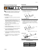
Repair - Parts Proportioning Pumps 312068M EN Proportioning pumps and hydraulic cylinders used on Hydraulic Proportioners. For professional use only. For professional use only. Not for use in explosive atmospheres. Important Safety Instructions Read all warnings and instructions in this manual and all supplied manuals. Save all instructions. Model 247576: 2000 psi (13.8 MPa, 138 bar) Maximum Working Pressure All other models: 3500 psi (24.
Models Contents Models . . . . . . . . . . . . . . . . . . . . . . . . . . . . . . . . . . . 2 Proportioning Pumps . . . . . . . . . . . . . . . . . . . . . 2 Hydraulic Cylinders . . . . . . . . . . . . . . . . . . . . . . . 2 Pumplines . . . . . . . . . . . . . . . . . . . . . . . . . . . . . 2 In-Plant Pumpline . . . . . . . . . . . . . . . . . . . . . . . . 2 Repair . . . . . . . . . . . . . . . . . . . . . . . . . . . . . . . . . . . . 3 Flushing . . . . . . . . . . . . . . . . . . . . . . . . . . . .
Repair Repair Flushing Flush equipment only in a well-ventilated area. Do not spray flammable fluids. Do not turn on heaters while flushing with flammable solvents. • Flush out old fluid with new fluid, or flush out old fluid with a compatible solvent before introducing new fluid. • Use lowest possible pressure when flushing. • To flush entire system, circulate through gun fluid manifold (with manifold removed from gun). • Always leave some type of fluid in system. Do not use water.
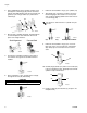
Repair Pumpline Disassembly Pumpline Reassembly 1. Remove plug fitting (206) from lube cylinder (205). 1. Slide the hydraulic piston (104) in the hydraulic cylinder (201) out to its left-most position. The left end of the left clevis (117) should be nearly in line with the left end of the spacers (113). See the following image. 2. Insert clevis pin removal tool 296607 through opening in lube cylinder (205) and screw tool into left clevis pin (219). Pull clevis pin out of clevis (117). 3.
Repair 6. Attach the clevis pin (219) to the clevis pin tool. Insert clevis pin through hole in lube cylinder and into the left clevis. 7. Gently tap end of clevis pin tool with hammer to slide clevis pin (219) into place. Remove clevis pin tool from clevis pin. 8. Insert four hex head cap screws (203) through holes in proportioning pump (202) and partially screw into spacers (113) in hydraulic cylinder (201). 10.
Repair Pump Base Disassembly Disassemble and clean pump base annually. For pumpline P7758-255773, disassemble and clean the pump base on every six months. 1. Relieve pressure, page 3. 2. Turn OFF the main disconnect and lock out power at the source. 3. Remove pump cap (19) from pump base (23), and remove o-ring (6): a. Remove outlet ball (4) and o-ring (9). b. Remove inlet ball cage (14), spring (22) and inlet ball (10). c. Remove inlet ball seat (11) and o-ring (9) from bottom of cavity. d.
Repair Piston and Cylinder Seals Reassembly CAUTION To prevent cross-contamination of the equipment’s wetted parts, never interchange component A (isocyanate) and component B (resin) parts. Piston Seal and Cylinder Seal Repair Kits are available. See Table 1 on page 17 to order the correct kits for your pump. Also see kit manual 312071. 1. Install piston rod seal (15); ensure u-cup faces piston rod (28) as shown in FIG. 1. Disassembly 28 15 18 1. Relieve pressure, page 3. 2.
Repair 3. Using supplied bolts in the cylinder seal kits, press seal (16) into outlet flange (26). Ensure seal faces cylinder. Assemble bushing (13) throat seal (29) and gasket (17) into flange retainer (27) and fasten to outlet flange. 29 16 7. Lubricate and assemble o-rings (1) to cylinder (12). 8. Tap cylinder (12) onto piston rod (28) as shown in the following figure. Be careful to not score piston seal. Continue tapping cylinder until it seats in bore of outlet flange (26).
Repair Hydraulic Cylinder 5. Using the 1 in. open-end wrench and the 1 in. impact wrench, rotate the baffle jam nut away from the right clevis until one of them breaks loose. For repairs, order Hydraulic Cylinder Repair Kit 296785. Disassembly TI11285a1 Tools Required • Two - 1 in. open-end wrench • Two - 1/2 in. open-end wrench • O-ring pick If the left clevis and baffle jam nut break loose from the hydraulic piston shaft: 6. Remove the clevis and baffle jam nut. 7.
Repair 17. Remove the right port block and rod bushing assembly. 18. Remove the rod bushings (103) from the port blocks (116). Reassembly Tools Required • Torque wrench set to 15 ft-lb (20 N•m) with 1 in. open-end attachment and 1/2 in. socket attachment • 1 in. open-end wrench • 1/2 in. open-end wrench 19. Using the o-ring pick, remove all rings and seals. If the right clevis breaks loose from the hydraulic piston shaft: 6. Remove the right clevis. 7.
Repair 7. Repeat the steps above to assemble the second rod bushing/port block assembly. Assemble Hydraulic Piston and Insert in Cylinder Assembling Items onto Piston Shaft 12. With the rod bushing (103) facing away from the cylinder (102), slide the port block and rod bushing assembly over the rod tool and onto the shaft. 8. Place wear ring (108) in the center channel of hydraulic piston (104). A 9.
Repair 18. Using the far, top tie-rod, attach cylindrical spacer (114) to the right side of the assembly. 24. With the lip of the adapter facing left, slide the adapter onto the left end of the hydraulic piston shaft. Installing Hex Clevises and Baffle Jam Nut 114 TI11282a 25. With the hex-side of the baffle jam nut facing away from the hex-head of the clevis, spin the baffle jam nut (122) onto the hex clevis (117). Leave one to two threads between the head of the clevis and the nut. 19.
Repair 34. Hold the left clevis stationary with a 1 in. wrench and break the baffle jam nut loose from the hydraulic piston shaft. CAUTION In the following step, do not over torque. 1 33. Hold the right clevis stationary with a 1 in. open-end wrench and, by turning the baffle jam nut with a 1 in. torque-wrench, torque the right clevis to 15 ft-lb (20 N•m) against the activator plate. 2 1 2 2 1 TI11285a 1 Hold stationary. 2 Rotate to torque the right clevis. TI11286a Hold stationary.
Repair butts against the retainer plate (101). Repeat for opposite end of tie rod. CAUTION In the following step, do not over torque. Assembling Manifold 36. Hold the left clevis stationary with a 1 in. open-end wrench to keep the cross-holes horizontal and torque the baffle jam nut against the hydraulic piston shaft to 15 ft-lb (20 N•m) using a torque wrench. 39. Insert pipe plugs (127) into manifold (125). 40. Insert o-rings (128) into bottom holes of manifold. 41.
Parts Parts Pumpline 203 202 219 201 219 207 205 204 206 208 202 203 204 ti13870a Pumpline Assembly Ref Description 288638 288639 P7758-255773 201 202 203 204 205 206 207 208 219 CYLINDER, hydraulic PUMP, proportioner SCREW, cap, socket head PACKING, o-ring CYLINDER, lube FITTING, plug FITTING, elbow, 90 degree FITTING, elbow, 90 degree PIN, clevis 295027 247375 295824 106258 261863 295829 295826 295397 296653 295027 247377 295824 106258 261863 295829 295826 295397 296653 247624 247375 02
Parts Piston and Cylinder Seals A Side Shown 2 19 36 27 6 9 29 4 6 14 34 13 2 22 24 10 11 35 16 9 26 4 4 17 31 12 1 5 8 23 TI9780b 3 Piston Assembly B side of pump is same as A side except items 31, 34, 35, and 36 are reversed. 1 Apply supplied sealant to threads 2 Torque to 75 ft-lb (101.3 N•m) 3 Torque to 45 ft-lb (60.
Parts Ref. 1 2 3 4 Part 5 261866 6 8 261865 9 10 107167 11 12 13 14 105445 193395 261899 15 Description Qty O-RING, PTFE 2 O-RING, TPE 2 CAP, piston 1 BALL, valve, outlet, SST; 1/2 in. (13 1 mm) diameter WASHER, flat, packing support 1 (4 pack) O-RING, PTFE 1 SCREW, hex hd cap; 3/8-24 x 9.0 1 in. (228 mm) (4 pack) O-RING, PTFE 2 BALL, valve, inlet, SST; 1 in.
Parts Hydraulic Cylinder 126 127 125 4 128 116 109 111 113 3 101 120 121 122 112 110 103 105 117 2 1 3 116 109 110 112 103 111 115 105 118 102 106 107 117 104 106 107 2 108 114 119 3 101 18 1 3 1 Apply high strength thread sealant to threads. 2 Apply primer to threads to speed curing. 3 Torque to 15 ft-lb (20 N•m). See assembly section for correct procedure. 4 On Model 247624, rotate manifold 180 degrees about the vertical axis. 5 Part used only on Model P7758-255773.
Parts Ref. 101 102 103 104 105 106 107 108 109 110 111 112 113 114 115 116 117 118 119 120 Part 295029 295030 295031 296642 295640 295641 295642 296643 158776 295644 295645 296644 295032 261502 295034 295035 261864 261862 Description Qty.
Parts 20 312068M
Technical Data Technical Data Category Maximum fluid temperature Data Model 247576: 2000 psi (13.8 MPa, 138 bar) All other models: 3500 psi (24.0 MPa, 240 bar) 120°F (49°C) Viscosity range 250-1500 centipoise Maximum material inlet pressure 400 psi (2.
Graco Standard Warranty Graco warrants all equipment referenced in this document which is manufactured by Graco and bearing its name to be free from defects in material and workmanship on the date of sale to the original purchaser for use. With the exception of any special, extended, or limited warranty published by Graco, Graco will, for a period of twelve months from the date of sale, repair or replace any part of the equipment determined by Graco to be defective.