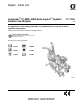
Repair - Parts List LineLazer™ IV 3900, 5900 Auto-Layout™ System Airless Line Stripers 312195K EN For application of line striping materials. For professional use only. Not for use in explosive atmospheres. 3300 psi (22.8 MPa, 228 bar) Maximum Working Pressure Important Safety Instructions Read all warnings and instructions in this manual. Save these instructions. See page 2 for model information.
Models Contents Models . . . . . . . . . . . . . . . . . . . . . . . . . . . . . . . . . . . . . . . . . 2 Warnings . . . . . . . . . . . . . . . . . . . . . . . . . . . . . . . . . . . . . . . 3 Tip Selection . . . . . . . . . . . . . . . . . . . . . . . . . . . . . . . . . . . . 5 Maintenance . . . . . . . . . . . . . . . . . . . . . . . . . . . . . . . . . . . . 6 Troubleshooting . . . . . . . . . . . . . . . . . . . . . . . . . . . . . . . . . 7 Auto-Layout Can Actuator Adjustment. . . . . . . . . . .
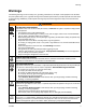
Warnings Warnings The following warnings are for the setup, use, grounding, maintenance, and repair of this equipment. The exclamation point symbol alerts you to a general warning and the hazard symbol refers to procedure-specific risk. Refer back to these warnings. Additional, product-specific warnings may be found throughout the body of this manual where applicable. WARNING FIRE AND EXPLOSION HAZARD Flammable fumes, such as solvent and paint fumes, in work area can ignite or explode.
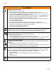
Warnings WARNING EQUIPMENT MISUSE HAZARD Misuse can cause death or serious injury. • Do not operate the unit when fatigued or under the influence of drugs or alcohol. • Do not exceed the maximum working pressure or temperature rating of the lowest rated system component. See Technical Data in all equipment manuals. • Use fluids and solvents that are compatible with equipment wetted parts. See Technical Data in all equipment manuals. Read fluid and solvent manufacturer’s warnings.
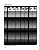
Tip Selection Tip Selection in. (cm) * LL5213* 2 (5) LL5215* 2 (5) in. (cm) in. (cm) in.
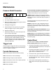
Maintenance Maintenance Pressure Relief Procedure 1. Engage trigger lock. 2. Turn engine ON/OFF switch to OFF. 3. Move pump switch to OFF and turn pressure control knob fully counterclockwise. 4. Disengage the trigger lock. 5. Hold a metal part of the gun firmly to a grounded metal pail. Trigger the gun to relieve pressure. 6. Engage the trigger lock. 7. Open pressure drain valve. Leave valve open until you are ready to spray again. 8.
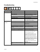
Troubleshooting Troubleshooting Problem E=XX is displayed. Engine won't start. Cause Solution Fault condition exists. Determine fault correction from table, page 20. Engine switch is OFF. Turn engine switch ON. Engine is out of gas. Refill gas tank. Honda Engines Owner's Manual. Engine oil level is low. Try to start engine. Replenish oil, if necessary. Honda Engines Owner's Manual. Spark plug cable is disconnected or damaged. Connect spark plug cable or replace spark plug. Cold engine.
Troubleshooting Problem Pump output is low. Excessive paint leakage into throat packing nut. Cause Solution Strainer (34f) is clogged. Clean strainer. Piston ball is not seating. Service piston ball. See pump manual. Piston packings are worn or damaged. Replace packings. See pump manual. O-ring in pump is worn or damaged. Replace o-ring. See pump manual. Intake valve ball is not seating properly. Clean intake valve. See pump manual. Intake valve ball is packed with material.
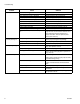
Troubleshooting Problem Cause Solution Clutch squeaks each time Clutch surfaces are not matched to each other clutch engages. when new and may cause noise. Clutch surfaces need to wear into each other. Noise will dissipate after a day of run time. High engine speed at no load. Misadjusted throttle setting. Reset throttle to 3600 engine rpm at no load. Worn engine governor. Replace or service engine governor. Gallon counter not working. Broken or disconnected wire. Check wires and connections.
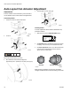
Auto-Layout Can Actuator Adjustment Auto-Layout Can Actuator Adjustment Adjustments 4 Carefully tighten screws. Verify gap. The can actuator is set at the factory. If the dot size is not as desired, do the coarse and/or fine adjustments. Coarse Adjustment 1 Locate four screws on side of holder base. ti10073a Fine Adjustment If coarse adjustment did not achieve desired dot size, proceed as follows: ti10070a 2 1 Start striper and move to PARKING MODE display.
Bearing Housing and Connecting Rod Bearing Housing and Connecting Rod Removal 2. Assemble connecting rod (26) and bearing housing (22). 3. Clean mating surfaces of bearing and drive housings. 1. Relieve pressure, page 6. 4. Align connecting rod with crank (B) and carefully align locating pins (F) in drive housing (24) with holes in bearing housing (22). Push bearing housing onto drive housing or tap into place with plastic mallet. 2. FIG. 2. Remove screws (187) and front cover (83). 3.
Drive Housing Drive Housing Removal Installation 1. Liberally apply bearing grease (supplied with replacement gear cluster) to gear cluster (23) and to areas called out by note 2. 2. Place bronze colored washer (24g) on shaft protruding from large shaft of drive housing (24). Place silver colored washer (24h) on pinion housing. Clean mating surfaces of pinion and drive housings. Align gears and push new drive housing straight onto pinion housing and locating pins (A). 1. Relieve pressure, page 6. 2. FIG.
Pinion Assembly/Clutch Armature/Clamp Pinion Assembly/Clutch Armature/Clamp Pinion Assembly/Clutch Armature Removal 175 172 E Pinion Assembly E If pinion assembly (25) is not removed from clutch housing (85), do steps 1 through 3. Otherwise, start at 4. TI5481b TI5987c FIG. 5 1. Remove drive housing, page 12. 2. FIG. 12. Remove junction box (226). 7. FIG. 6. Remove retaining ring (25e). 3. FIG. 11. Disconnect pump stroke sensor and clutch cables. 8. Tap pinion shaft (25d) out with plastic mallet.
Pinion Assembly/Clutch Armature/Clamp Installation Clamp Clutch Armature Removal 1. FIG. 8. Lay two stacks of two dimes on smooth bench surface. 1. Do Engine Removal. 2. Drain gasoline from tank according to Honda manual. 2. Lay armature (87) on two stacks of dimes. 3. Press center of clutch down on bench surface. 3. Tip engine on side so gas tank is down and air cleaner is up. 4. FIG. 9. Loosen two screws (175) on clamp (82), 87 5. Push screwdriver into slot in clamp (82) and remove clamp. 0.
Clutch Housing Clutch Housing Removal 1. FIG. 10. Remove four cap screws (186) and lock washers (188) which hold clutch housing (85) to engine. 2. Remove screw (177) from under mounting plate (96). 3. Pull off clutch housing (85). Installation 1. FIG. 10. Push on clutch housing (85). 2. Install four cap screws (186) and lock washers (188) and secure clutch housing (85) to engine. Torque to 180 in-lb (20.3 N•m). 3. Install capscrew (177) from beneath mounting plate (96). Torque to 20 ft-lb (27.1 N•m).
Engine Engine Removal 1. 185 Remove Pinion Assembly/Clutch Armature/Clamp and Clutch Housing. See pages 13 - 15. Engine 2. FIG. 12. Remove junction box (226). 3. FIG. 11. Disconnect all necessary wiring. 223 4. FIG. 12. Remove screw (177). Remove two screws (117), locknuts (118), and ground conductor (223, 260) from base of engine (185). 117 5. Lift engine carefully and place on work bench. 96 Ref. 118 ti6398b All service to the engine must be performed by an authorized HONDA dealer.
Pressure Control Pressure Control On/Off Switch 4. Press locking tab on ON/OFF switch connector (B) and disconnect from control board. Note: A complete wiring diagram is on page 34. 5. Press in on two retaining tabs on each side of ON/OFF switch and remove switch. Removal Installation 1. Install ON/OFF switch (15g) so tabs of switch snap into place on inside of pressure control housing. 2. Connect ON/OFF switch connector (B) to J3 on control board. 1. Relieve pressure, page 6. 2. FIG. 13.
Pressure Control Control Board Installation Removal 1. FIG. 13. Install o-ring (217) and pressure control transducer (216) in filter manifold (40). Torque to 35-45 ft-lb. 2. Connect transducer lead (C) to control board (15d). 3. Install control cover (31) with two screws (125). 1. Relieve pressure, page 6. 2. FIG. 13. Remove two screws (125) and control cover (31). Pull display connector wings open on control board and pull display connector out. Pressure Adjust Potentiometer Removal 3. FIG.
Trigger Sensor Adjustment Engine Stop Switch Note: A complete wiring diagram is on page 34. Removal 4. Press in on two retaining tabs on each side of ENGINE STOP switch and remove switch. Installation 1. Install ENGINE STOP switch (15f) so tabs of switch snap into place on inside of pressure control housing. 1. Relieve pressure, page 6. 2. FIG. 13. Remove two screws (125) and cover (31). 2. Install cover (31) with two screws (125). 3. Remove two spade connectors from ENGINE STOP switch (15f).
Control Board Diagnostics Control Board Diagnostics Digital Display Messages Relieve pressure before repair; page 6. No display does not mean that sprayer is not pressurized. Display Sprayer Operation No Display Sprayer may be pressurized. Loss of power or display not connected. Sprayer may be pressurized. Pressure less than 200 Increase pressure as needed. psi (14 bar, 1.4 MPa). ti6314a psi bar MPa ti6315a Indication Action Check power source. Relieve pressure before repair or disassembly.
Displacement Pump Displacement Pump Installation Removal 1. Flush pump. 2. Relieve pressure, page 6. 3. FIG. 15. Cycle pump piston rod (A) to lowest position. If pin works loose, parts could break off due to force of pumping action. Parts could project through the air and result in serious injury or property damage. Make sure pin and retaining spring are properly installed. 4. FIG. 15. Remove suction tube (34) and hose (100).
Parts Parts LineLazer IV Page 32 Page 26 Page 30 Page 28 Page 24 Page 31 ti10062a 22 312195K
Parts - Drive and Pinion Housing Assemblies Parts - Drive and Pinion Housing Assemblies Ref No. 24 and 25 Ref No. 24: Drive Housing Assembly 287467 for LineLazer IV 3900; Drive Housing Assembly 287469 for LineLazer IV 5900 Ref 24 24g 24h Part Description 287467 HOUSING, drive (3900) 287469 HOUSING, drive (5900) WASHER 107089 LineLazer IV 3900 194173 LineLazer IV 5900 WASHER 116191 LineLazer IV 3900 116192 LineLazer IV 5900 Qty 1 1 1 1 1 1 Ref No.
Parts - Drive and Pinion Housing Assemblies LineLazer IV Auto-Layout System 268 57 144 141 267 33 27 264 35 177 129 107 154 5 177 232 77 177 93 77 134 153 94 14 108 42 112 74 108 273 177 70 121 115 13 117 58 153 73 60 115 66 272 120 68 108 277 117 51 130 127 142 122 115 117 16 TI14597A 24 312195K
Parts - Drive and Pinion Housing Assemblies LineLazer IV Auto-Layout System Ref 5 13 14 16 27 28 33 35 42 51 57 58 60 66 68 70 73 74 77 93 94 107 108 109 115 Part 237686 245225 245798 287623 287417 287622 287590 119771 108471 193405 194310 195134 196176 15K357 15J088 198891 198930 198931 114271 15F577 15F576 178342 101566 102478 108868 312195K Description Qty WIRE, ground assembly w/ clamp 1 HOSE, cpld, 3/8 in. x 50 1 HOSE, cpld, 1/4 in.
Parts - Drive and Pinion Housing Assemblies LineLazer IV Auto-Layout System Models 253920, 253921 247 86 172 170 Ref 25, page 23 23 Ref 24, page 23 83 189 189 190 182 158 233 234 185 178 181 235 259 236 187 183 189 179 85 188 186 26 188 88 212 ti6405d 117 175 172 81 22 175 84 172 258 82 117 87 249 100 248 96 108 60 114 21 34 (Detail E) 59 260 34m 34n 177 34g 223 261 118 226 34d 34h 34b 34k 34j 34d 34c 174 34a 34e Ref 16, page 24 34f Detail E (12) TI6405c 26 3
Parts - Drive and Pinion Housing Assemblies LineLazer IV Auto-Layout System Ref 21 22 23 26 34 34a 34b 34c 34d 34e 34f 34g 34h 34j 34k 34m 34n▲ 59 60 81† 82 83 84 84 85 85 86† Part 277069 277070 287714 287715 287653 287460 287719 287720 245730 15F149 185381 110194 101818 15F513 181072 245731 245798 114958 196180 195119 119695 196176 193680 287521 287511 192723 193031 15E535 15E277 87† 88 96 100 108 114 117 118 158 170† 172† 174 175 177 178 179 181 182 183 185 183401 15F583 245797 101566 108851 110837 11
Parts - Drive and Pinion Housing Assemblies LineLazer IV Swivel Wheel Assembly 240719 Models 253920 and 253921 Ref 141 (page 24) 56 142 117 146 1 121 127 130 133 7 113 153 10 54 128 Ref 16 (page 24) 108 106 133 Ref 141 132 127 147 116 46 55 52 139 130 110 1 209 208 65 Ref 6 (Detail D) 6 F 140 135 145 Detail D 131 1 Install washers (130) concave surface to inside.
Parts - Drive and Pinion Housing Assemblies LineLazer IV Swivel Wheel Assembly 240719 65133 Ref 6 7 10* 46 52 54 55 56 65 106 108 110 113 116 117 121 127 128 130 131 132* 133* 135 139 140 141 142 145 146 147 153 208 209* Part 240942 240991 15G952 181818 193528 193661 193662 15F910 198606 100731 101566 15J603 108483 110754 110837 111040 112405 112776 119563 113471 113484 113485 113962 114548 114549 241445 114648 114681 114682 114802 114982 193658 120476 Description SHAFT, fork BRACKET, caster, front BRAC
Parts - Drive and Pinion Housing Assemblies LineLazer IV Auto-Layout System Models 253920 and 253921 108 153 49 136a 136 95 219 44 112 1 104 161 8b 8f 105 47 8 Ref 14 8d 8c 8e 8b 8a ti6494a 4 160 119 71 72 Ref 144 (page 24) 227 Ref 161 119 126 162 89 163 71 165 166 164 17 TI6497a 30 312195K
Parts - Drive and Pinion Housing Assemblies LineLazer IV Auto-Layout System Ref 1 4 8 8a 8b 8c 8d 8e 8f 17* Part 224052 248157 287570 287569 102040 15F214 15F209 15F210 15F211 245733 44 47 49 71 72 89* 95 104 15F212 15F213 188135 198895 198896 15A644 15K198 119647 Description Qty BRACKET, support gun 1 GUN, flex, basic 1 HOLDER ASSEMBLY, gun 1 HOLDER, gun 1 NUT, lock 4 LEVER, actuator 1 STUD, pull, trigger 1 STUD, pivot 1 STUD, cable 1 KIT, trigger handle repair (includes 1 17.
Parts - Drive and Pinion Housing Assemblies LineLazer IV Auto-Layout System 103 Models 253920 and 253921 15u 15k 15o 15g 191 190 15d 15c 15b 15m 15s 15w 268 269 15f 15x 15a 15r 15n 15t 31 123 125 41 167 125 37 29 11 40 262 62 271 76 2a 97 259 38 124 13 2b 2d 2c 62 Ref 14 32 2 64 Ref 100 ti17487b 312195K
Parts - Drive and Pinion Housing Assemblies LineLazer IV Auto-Layout System Ref 2* 2a 2b 2c 2d 11* 13 15 Part 245103 193709 193710 116424 114708 244067 245225 289264 15a 15b 15c 15d 15f 15g 15k 15m 15n 15o 15r 15s 15t 15u 15w 15x 29 31 37* 38* 40* 41* 62 64 76 97 103 123 124* 125 167* 190 191 225 259* 287692 119736 15F777 15F776 196179 15F589 15C766 15G563 15H561 287285 196178 196181 104813 15K102 116719 15F814 111457 117501 117285 115999 176754 15A464 287172 262 268 269 271 111801 198650 256219 11134
Auto-Layout System Wiring Diagram Auto-Layout System Wiring Diagram 240997 119579 GREY GREY VIOLET VIOLET/WHITE (ref. 268) WHITE/BLACK 1. BLUE 2. BLACK 3. WHITE/BLUE 4. BLACK/WHITE EEN EEN GR E/GR IT WH ti10235a FIG.
Technical Data Technical Data Honda GX120 Engine (3900) Power Rating @ 3600 rpm ANSI. . . . . . . . . . . . . . . . . . . . . . . . . . . . . . . . . . . . . . DIN 6270B/DIN 6271 NA . . . . . . . . . . . . . . . . . . . . . . . . . . . . . . . . . . . . NB . . . . . . . . . . . . . . . . . . . . . . . . . . . . . . . . . . . . Honda GX160 Engine (5900) Power Rating @ 3600 rpm ANSI. . . . . . . . . . . . . . . . . . . . . . . . . . . . . . . . . . . . . . DIN 6270B/DIN 6271 NA . . . . . . . . . . . . . . .
Dimensions Dimensions LineLazer IV 3900 Auto-Layout System Model 253920, 255151 Striper Weight (dry, without packaging) . . . . . . 212 lb (96 kg) Height. . . . . . . . . . . . . . . . . . . . . . . 40 in. (101.6 cm) Length . . . . . . . . . . . . . . . . . . . . . . 65 in. (165.1 cm) Width . . . . . . . . . . . . . . . . . . . . . . . . 32 in. (81.3 cm) Model 253953, 255152 Striper with 2nd Gun Kit Weight (dry, without packaging) . . . . . 222 lb (101 kg) Height. . . . . . . . . . . . . . . . . . . . . .
Dimensions 312195K 37
Warranty Graco warrants all equipment referenced in this document which is manufactured by Graco and bearing its name to be free from defects in material and workmanship on the date of sale to the original purchaser for use. With the exception of any special, extended, or limited warranty published by Graco, Graco will, for a period of twelve months from the date of sale, repair or replace any part of the equipment determined by Graco to be defective.