Application Methods LineLazer™ IV 3900, 5900, 200HS Auto-Layout™, and 250SPS System Airless Line Stripers 312307E EN - For the application of line striping materials. For professional use only. Not for use in explosive atmospheres. 3300 psi (22.8 MPa, 228 bar) Maximum Working Pressure. Important Safety Instructions Read all warnings and instructions in the Operations Manual 312190. Save these instructions.
Table of Contents Quick Guide - LineLazer IV Auto Layout System . 3 Quick Guide - LLIV 250SPS . . . . . . . . . . . . . . . . . . 4 LineLazer IV Auto-Layout System . . . . . . . . . . . . . 5 LLIV 250SPS . . . . . . . . . . . . . . . . . . . . . . . . . . . . . . . 5 Calibration . . . . . . . . . . . . . . . . . . . . . . . . . . . . . . . . 6 Measure Mode . . . . . . . . . . . . . . . . . . . . . . . . . . . . . 7 Basic Stall Layout: Parking Mode . . . . . . . . . . . . .
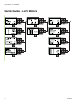
Quick Guide - LineLazer IV Auto Layout System Quick Guide - LineLazer IV Auto Layout System ti8387b_front 312307E 3
Quick Guide - LLIV 250SPS Quick Guide - LLIV 250SPS 4 312307E
312307E 5 Gun and 286111 Spray Tip LLIV 250SPS ti10100a Spray Module with Aerosol Chalk Can LineLazer IV Auto-Layout System PSK '27 6,=( ! 67$// 6,=( ҋ ! SVL 3DUNLQJ /D\RXW 0RGH Remote Switch Gun Trigger Control Calibration Bar Calibration Bar & Rear Gun Mount 02'( Display 6(783 Display
312307E ti10101a FINISH Minimum 25 ft precision course Calibration START CHANGE UNITS changes all displayed values to metric or standard units of measure. IMPORTANT NOTE: For best results, calibrate to a minimum of 25 ft. Use only steel measuring tape. Precise start and stop are necessary. Calibration distance above 100 ft is not recommended due to inaccuracy with setting up the course. Tire air pressure variations can negatively impact accuracy of unit. Press REMOTE SWITCH to START calibration.
312307E 7 FINISH ti10102a START NOTE: The striper measures moving forward or reverse. Press REMOTE SWITCH to START. Press REMOTE SWITCH to FINISH. Measurements automatically increment down on screen, last measurements display at all times. MEASURE MODE At any time while in MEASURE MODE, momentarily hold down REMOTE SWITCH to apply dot. Holding down REMOTE SWITCH will produce continuous dotted line 1 foot dot spacing when moving, used for pre-marking.
312307E ti10103a 15 stalls Establishing outer boundary with reference dots Basic Stall Layout: Parking Mode START Establish enough reference dots to guide striper for applying stall lines. In this case, 18 ft from inner curbing. PARKING MODE Press REMOTE SWITCH to START and FINISH. 18 feet FINISH NOTE: Minimum pressure on LLIV 250SPS is 1000 psi. NOTE: Minimum RPM for placing dots is 2600. NOTE: For Best results, always dot in the same direction.
312307E 9 ti10104a START 16 Stalls FINISH NOTE: System automatically transfers the calculated STALL SIZE from PARKING CALC to PARKING MODE screen. Use up/down arrows to adjust number of stalls as desired. Press remote switch to start measuring. Follow the established 18 ft reference dots, measure from start to finish. Press remote switch to stop measuring. PARKING CALC Press REMOTE SWITCH to START and FINISH calculation. IMPORTANT NOTE: Start-point and finish-point accuracy is critical.
312307E ti10105a START Mark dots at beginning of each stall 16 Stalls Basic Stall Layout: Parking Mode NOTE: System automatically transfers the calculated STALL SIZE from PARKING CALC screen if desired. Utilizing calculated stall size, apply dots, traveling from start to finish. PARKING MODE Press REMOTE SWITCH to START and FINISH dots.
312307E 11 ti10106a START 9 ft Mark dots at end of each stall 16 Stalls Basic Stall Layout: Parking Mode Establish first stall perpendicular to curb as shown (if curbing does not allow room for striper). Press remote switch at start while following curbing as a reference applying evenly spaced dots. Press remote switch at finish to stop dots. PARKING MODE Press REMOTE SWITCH to START and FINISH dots.
312307E ti10107a Paint lines (connect the dots) Basic Stall Layout: Striping Mode STRIPING MODE Simply connect the dots with your sprayer.
312307E 13 ti10108a START Establish the center line and outer boundary first Island Stall Layout: Parking Mode START NOTE: The striper measures moving forward or reverse, as shown, placing evenly spaced dots at desired spacing. Establish enough reference dots to guide striper for applying stall lines by using PARKING MODE measuring 18 ft out from centerline. PARKING MODE Press REMOTE SWITCH to start and stop dots.
312307E ti10109a Place dots at the beginning of each stall line 32 Stalls Island Stall Layout: Parking Mode NOTE: See Basic Stalls section (pages 4-8) to automatically measure and calculate stall size. PARKING MODE Press REMOTE SWITCH to start and stop dots. START START NOTE: Minimum pressure on LLIV 250SPS is 1000 psi. NOTE: Minimum RPM for placing dots is 2600. NOTE: For Best results, always dot in the same direction.
312307E 15 ti10110a Paint lines (connect the dots) Island Stall Layout: Striping Mode STRIPING MODE Simply connect the dots with the striper.
312307E ti10113b Place evenly spaced dots at beginning of each stall Radius Stall Layout: Parking Mode 15 Stalls START Establish enough reference dots to guide striper for measuring and applying stall lines. In this case, 18 feet from inner curbing. PARKING MODE Press REMOTE SWITCH to START and FINISH. 18 ft FINISH NOTE: Minimum pressure on LLIV 250SPS is 1000 psi. NOTE: Minimum RPM for placing dots is 2600. NOTE: For best results, always dot in the same direction.
312307E 17 ti10411a START Measure inner perimeter distance FINISH NOTE: System automatically transfers the calculated STALL SIZE from PARKING CALC to PARKING MODE screen. Use up/down arrows to adjust correct number of stalls. New parking stall size will display under STALL SIZE. Establish first stall if curbing does not allow room for striper (in this case 15 less 1 = 14 for the calculation).
312307E START ti10412a Mark dots at end of each stall FINISH NOTE: System automatically transfers the calculated STALL SIZE from PARKING CALC to PARKING MODE screen. Establish first stall perpendicular to curb as shown (if curbing does not allow room for striper). Utilizing calculated stall size, apply dots, traveling from start to finish. PARKING MODE Press REMOTE SWITCH to START and FINISH dots.
312307E 19 ti10413a START Measure outer perimeter distance FINISH NOTE: System automatically transfers the calculated STALL SIZE from PARKING CALC to PARKING MODE screen. Use up/down arrows to adjust correct number of stalls. Press remote switch at start to begin measuring. Follow the established 18 ft reference dots measuring from start to finish. Press remote switch again to stop measuring. PARKING CALC Press REMOTE SWITCH to START and FINISH measuring.
312307E ti10414a START Place evenly spaced dots at beginning of each stall 15 Stalls Radius Stall Layout: Parking Mode NOTE: System automatically transposes the calculated STALL SIZE from PARKING CALC to PARKING MODE screen. Utilizing calculated stall size, apply dots traveling from start to finish. PARKING MODE Press REMOTE SWITCH to START and FINISH dots.
312307E 21 ti10116b Paint lines Radius Stalls STRIPING MODE Simply connect the dots with the striper.
312307E ti10117b START Establish the center line and outer boundary Angle Stall Layout: Parking Mode START NOTE: The striper measures moving forward or reverse, as shown, placing evenly-spaced dots at desired spacing. Establish enough reference dots to guide striper for applying stall lines by using PARKING MODE measuring 18 ft out from centerline. PARKING Mode Press REMOTE SWITCH to START and FINISH dots. 32 Stalls NOTE: Minimum pressure on LLIV 250SPS is 1000 psi.
312307E 23 ti10118a Measure outer boundary 14 Stalls 14 Stalls 75° 4.82 9.00 NOTE: System automatically transfers calculated “dot spacing” from ANGLE CALC to PARKING MODE screen. ANGLE CALC Press REMOTE SWITCH to adjust desired angle. Use up/down arrows to set desired STALL DEPTH and STALL SIZE. System automatically calculates “offset” and “dot spacing”.
312307E ti10119a FINISH FINISH Mark dots at end of each stall 14 Stalls Angle Stall Layout: Parking Mode If necessary, use PARKING CALC to determine how many 9.32 ft parking stalls will fit. PARKING MODE Press REMOTE SWITCH to START and FINISH dots.
312307E 25 ti10120a Paint lines (connect the dots) Angle Stall Layout: Striping Mode STRIPING MODE Simply connect the dots with the striper.
312307E ti10121a START Establish the boundary and apply dots at desired spacing Cross Hatch Layout: Parking Mode 6 feet Place dots around perimeter of area. Adjust STALL SIZE to achieve desired cross hatch spacing. PARKING MODE Press REMOTE SWITCH to START and FINISH dots. 36 feet 3 feet FINISH NOTE: Minimum pressure on LLIV 250SPS is 1000 psi. NOTE: Minimum RPM for placing dots is 2600. NOTE: For Best results, always dot in the same direction.
312307E 27 ti10122a Paint lines (connect the dots) Cross Hatch Layout: Striping Mode Paint interior by connecting the dots. If ends are rounded as shown, make sure you establish this before painting. STRIPING MODE Simply connect the dots with the striper.
312307E ti10123a Paint perimeter (connect the dots) STRIPING MODE Large or small, cross hatching jobs can be simplified by following these simple steps, eliminating the inconsistencies found on many job sites today.
312307E 29 ti10126a 8.00’ Paint lines (connect the dots) 8.00’ 4.00’ 4.00’ 8.00’ 8.00’ OTHER USES: • Multiple spaced handicap stall layout • Double line stalls MARKER MODE Automatic marker layout example shows typical lane line layout for reflective markers. Set space sizes up to 8 consecutive measurements. By leaving zeros in any space, AutoLayout will skip to the next measurement in a continuous loop. 16.00’ 48.
312307E ti10128a Skip line Line Layout: Road Mode ROAD MODE Automatic skipline layout for roads, bike trails, and airports.
Notes Notes 312307E 31
Graco Standard Warranty Graco warrants all equipment referenced in this document which is manufactured by Graco and bearing its name to be free from defects in material and workmanship on the date of sale to the original purchaser for use. With the exception of any special, extended, or limited warranty published by Graco, Graco will, for a period of twelve months from the date of sale, repair or replace any part of the equipment determined by Graco to be defective.