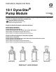
Instructions, Repair and Parts 10:1 Dyna-Star Pump Module ® 312349G ENG Provides lubricant flow and pressure to operate a single line parallel automatic lubrication system. For automatic lubrication systems only. Important Safety Instructions Read all warnings and instructions in this manual. Save these instructions.
Warnings Warnings The following warnings are for the setup, use, grounding, maintenance, and repair of this equipment. The exclamation point symbol alerts you to a general warning and the hazard symbol refers to procedure-specific risk. Refer back to these warnings. Additional, product-specific warnings may be found throughout the body of this manual where applicable.
Warnings WARNING PRESSURIZED EQUIPMENT HAZARD Fluid from the gun/dispense valve, leaks, or ruptured components can splash in the eyes or on skin and cause serious injury. • Follow Pressure Relief Procedure in this manual, when you stop spraying and before cleaning, checking, or servicing equipment. • Tighten all fluid connections before operating the equipment. • Check hoses, tubes, and couplings daily. Replace worn or damaged parts immediately.
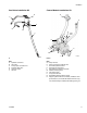
Unpacking Unpacking Pump Module Operation (See FIG. 4, page 8) The Dyna-Star pump module was carefully packaged for shipment by Graco. When the package arrives, perform the following procedure to unpack the units: 1. Inspect the shipping box carefully for shipping damage. Contact the carrier promptly if damage is discovered. 2. Unseal the box and inspect the contents carefully. There should not be any damaged parts. 3. Compare the packing slip against all items included in the box.
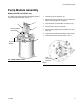
Pump Module Assembly Pump Module Assembly Models 247706 and 247707 only For divider valve-based automatic lubrication systems. (Unless otherwise indicated, see FIG. 1). 1. Install Pump (D) on Reservoir (P). 2. Remove Vent Valve Hydraulic Control (J) fitting and replace with Plug (R) (FIG. 6, page 9). D 3. Install Hydraulic Control Module on Reservoir (P). G Pressure Relief Kit 247902 4. Connect Tank Line (G) to Pump (D). H 5. Connect Pump High Pressure Hydraulic Line (H) to Pump (D). 6.
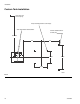
Installation Installation Read instruction manual 312350 BEFORE installing this product. • Be sure unit is securely mounted before operation. • Do not lift pressurized equipment. Grounding (for non-mobile installation) (See FIG. 3 below) CAUTION The hydraulic supply must be 10µ filtered or better and supply 0.5 - 3.0 gpm (1.9 - 11.4 lpm) at 300 psi - 3500 psi (21 bar - 241 bar (2.1 MPa - 24 MPa). 1. Install Ball Valve (AA) (user provided) in the 3/8-inch High Pressure Hydraulic Line (X). 2.
Installation Hydraulic Control Module for Custom Tank Installation (Unless otherwise indicated, see FIG. 5 and FIG. 6, page 9) 1. Mount control module on a flat, sturdy surface per the recommended configuration (Fig. 2, page 8). 2. Connect Pump Tank Line (G) to pump hydraulic outlet port. 3. Connect Vent Valve Hydraulic Control (J) connection to the hydraulic control line (A). 4. Connect the Pump High Pressure Hydraulic Line (H) to the pump hydraulic input port. 5.
Installation Typical Installation The installation shown in Figures 4, 5, 6 and 7 are only a guide for selecting and installing system components. Contact your Graco distributor for assistance in planning a system to suit your needs.
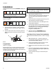
Installation Vent Valve Installation Kit Control Module Installation Kit G B A H E C D R F J Vent Port Q * K P M L ti9647a FIG. 5 FIG.
Installation Custom Tank Installation Vent return port 1/2-inch npt (f) Pump mounting Ø.343 or 5/16-18 (4x) Vent valve bracket weld locations Control module Ø.343 or 5/16-18 (2x) 18.0 Max 5.0 5.0 3.536 6.875 3.536 ti9653a FIG.
Operation Operation Pressure Relief Procedure Models 247706, 247707 (For these instructions see FIG. 4, page 8.) To reduce the risk of serious injury follow this pressure relief procedure whenever you (are): • • • • Instructed to relieve pressure. Shut off pump. Check, clean or service any of the system equipment. Install or clean the dispensing valve. Models 247444, 247574, 247456, 247457, 247970 1.
Operation Fill Reservoir (For these instructions see FIG. 4, page 8.) 5. Set hydraulic pressure to pump at lowest pressure needed (see Technical Data, page 18). 1. Connect lubricant supply hose from remote filling station pump to Fill Port (K). 6. Set hydraulic flow rate to pump at lowest rate needed to get desired results. 2. Connect High Pressure Lubricant Supply Line (G) to Vent Valve (U) outlet. 7. Read and follow instructions supplied with each system component. 3.
Service Service Use only Genuine Graco Repair Parts. See separate system component manuals for service instructions. For pump service see manual 312350. For vent valve service see manual 309099. Troubleshooting Problem System does not build sufficient pressure. Cause Solution Pump malfunction. Refer to manual 312350. Pump turned off too soon. Increase timer “pump on” setting. Increase hydraulic flow rate to pump. Solenoid malfunction. Repair or replace solenoid. Too low or no hydraulic supply.
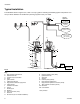
Parts Drawing Parts Drawing (See Parts List, page 17) Pump hydraulic inlet Pump hydraulic outlet 1a or 1b 3j Pump lubricant outlet 3e 3i 3l 3k 3d 3h 3f 3c 3a 3g ti10644a 14 312349G
Parts Drawing Parts Drawing Vent Valve Kit (2): 237170 Control Module Kit (4): 247538 (See Parts List, page 17) To pump lubricant outlet To pump hydraulic inlet 2h 4m 4p 2n 2g 2b 4u 4q To pump hydraulic outlet 4g* 4t 2f 2p 2a 2e 4k 4s* 2j 4c* 2i 2c 4d* 4r 2k 2d 4f* 4e* 4h* 4b 4a* 2m 4j 4n 2q 4a*/4h* Torque 40-43 ft-lbs (54-58 Nm) 4c*/4e* Torque 15-20 ft-lbs (20-27 Nm) 4d* Torque 20-25 ft-lbs (27-34 Nm) 4f* Torque 68-75 ft-lbs (92-102 Nm) 4g* Torque 22-24 ft-lbs (30-33 Nm) 4s*
Parts Drawing Parts Drawing Pressure Relief Kit (5): 247902 (for models 247706 and 247707 only) (See Parts List, page 17) 5h 5c 5b 5a 5j 5d 5e 5f 5g ti11458a 16 312349G
Parts List Parts List Model 247706: Dyna-Star 10:1 Pump Module, 60# for Single Line, Progressive, Automatic Lubrication Systems (includes items 1a, 3, 4, 5) Model 247707: Dyna-Star 10:1 Pump Module, 90# for Single Line, Progressive, Automatic Lubrication Systems (includes items 1b, 3, 4, 5) Model 247574: Dyna-Star 10:1 Pump Module, 60# for Single Line, Parallel, Automatic Lubrication Systems (includes items 1a - 4) Model 247444: Dyna-Star 10:1 Pump Module, 90# for Single Line, Parallel, Automatic Lubricati
Technical Data Technical Data Maximum hydraulic input pressure Pump wetted parts Vent valve wetted parts Reservoir wetted parts Maximum delivery @ 60 cpm Regulated hydraulic pressure operating range Models: 247444, 247574, 247456, 247457, 247970 Models: 247706, 247707 Hydraulic flow rate operating range Maximum hydraulic fluid temperature Lubricant outlet pressure range Models: 247444, 247574, 247456, 247457, 247970 Models: 247706, 247707 Reservoir overflow port size Reservoir fill port size Hydraulic inle
Dimensions Dimensions Model 247574 Hydraulic high pressure inlet 3/8 inch nps swivel Overflow port 1/2 inch npt Hydraulic tank 3/4 inch nps swivel ø15.0 inch Mounting Diagram (381 mm) 35.15 inch. (893 mm) Lubricant outlet 1/2 inch nps swivel 15.0 inch (381 mm) ti10646a 6- 7/16 inch holes 13 7/8 inch bolt circle Fill port 1/2 inch npt Model 247444 Hydraulic high pressure inlet 3/8 inch nps swivel Overflow port 1/2 inch npt Hydraulic tank 3/4 inch nps swivel Mounting Diagram ø15.
Dimensions Dimensions Model 247706 Lubricant outlet 1/2 inch Hydraulic high pressure inlet 3/8 inch nps swivel Pressure Relief Kit 247902 Overflow port 1/2 inch npt Hydraulic tank 3/4 inch nps swivel Mounting Diagram ø15.0 inch (381 mm) 35.15 inch (893 mm) 15.
Dimensions Notes 312349G 21
Graco Standard Warranty Graco Standard Warranty Graco warrants all equipment referenced in this document which is manufactured by Graco and bearing its name to be free from defects in material and workmanship on the date of sale to the original purchaser for use. With the exception of any special, extended, or limited warranty published by Graco, Graco will, for a period of twelve months from the date of sale, repair or replace any part of the equipment determined by Graco to be defective.