Operation and Maintenance PR70 ™ 2 Component Liquid Dispensing Systems PR70 All Models 3000 psi (21 MPa, 207 bar) Maximum Working Pressure 100 PSI (0.7 MPa, 7 bar) Maximum Air Inlet Pressure For Dispensing Multi-part Sealants and Adhesives. Not Designed for Use in Explosive Atmospheres. Important Safety Instructions Read all warnings and instructions in this manual.
Contents Contents .................................................... 2 PR70 Accessories .................................................. 3 Tank Level Sensing and Velocity Change (“ ”) Options (C6) .........................................................19 Supplied Manuals ..................................... 4 Password Setup / Clearing (C5) ............. 20 Related Manuals ....................................... 4 Setting/Clearing an Administrative Password:..........20 Warnings ................
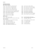
Models PR70 Accessories Mixer and Shroud Options LC0063 Mixer, 3/16 (6.5 mm) x 32, 10 Mixers with shroud LC0081 Mixer, 3/8 (9.8 mm) combo, 50 Mixers LC0057 Mixer, ¼ (6.5 mm) x 24, 10 Mixers with shroud LC0083 Mixer, 1/4 (6.5 mm) x 24 Luer Lock, 50 Mixers LC0058 Mixer, 3/8 (9.8 mm) x 24, 10 Mixers with shroud LC0082 Mixer, 3/16 (4.8 mm) x 32 Luer Lock, 50 Mixers LC0059 Mixer, 3/8 (9.8 mm) x 36, 10 Mixers with shroud LC0084 Mixer, 3/16 (4.8 mm) x 32, 250 Mixers LC0060 Mixer, 3/8 (9.
Manuals Supplied Manuals The following manuals will be supplied with the PR70. Refer to these documents for detailed machine information.
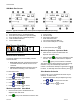
Warnings Warnings The following warnings are for the setup, use, grounding, maintenance, and repair of this equipment. The exclamation point symbol alerts you to a general warning and the hazard symbol refers to procedure-specific risk. Refer back to these warnings. Additional, product-specific warnings may be found throughout the body of this manual where applicable. WARNING ELECTRIC SHOCK HAZARD Improper grounding, setup, or usage of the system can cause electric shock.
Warnings WARNING EQUIPMENT MISUSE HAZARD Misuse can cause death or serious injury. • Do not operate the unit when fatigued or under the influence of drugs or alcohol. • Do not exceed the maximum working pressure or temperature rating of the lowest rated system component. See Technical Data in all equipment manuals. • Use fluids and solvents that are compatible with equipment wetted parts. See Technical Data in all equipment manuals. Read fluid and solvent manufacturer’s warnings.
Installation Installation General Information Accessories are available from Graco. Make certain all accessories are adequately sized and pressure-rated to meet your system needs. Figures 2 thru 4 are only a guide for identifying system components and for assisting in installation. Contact your Graco distributor or Graco Ohio Customer Service for assistance in designing a system to suit your particular needs. Unpacking 1. Inspect the shipping container carefully for damage.
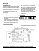
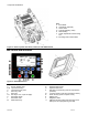
Component Identification Component Identification Key: A Dispense Valve (DV) B HMI (Human Machine Interface) C Static Mixer D Shield Locking Screw E Power Switch F Air Filter G Customer Input Receptacle H Protective Shield I Air Pressure Regulator J Ball Valve (Optional) K A and B Tanks (Onboard, Polyethylene versions illustrated).
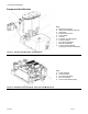
Component Identification Key: A Drive Block B Hydracheck (optional) C Check Valve D Cylinder (Metering Tube) E Rear Bearing F Phase Adjustment Screw/Locking Nut G Mounting Hole in Base Frame Figure 4: PR70 Top View with Shield, Tanks, DV and HMI Removed. HMI Control and Indicators Figure 5: PR70 HMI Controls Key: A B, D C E F G-J K L M Screen, Display Area Up and Down Keys Up and Down Key LED Enter Key LED Enter Key Soft Keys 1 thru 4 (Left to Right).
Run Screens HMI Main Run Screen Figure 6: Typical PR70 Main Run Screen (Shot and Operator Modes) Respectively) Key: A Shot Number Field (“x” in Operator Mode) B Shot Size Field (“XXXXXX” in Operator Mode) C Shot weight/mass unit of measure (Grams). D Tank Fill Status Indicators E Pistons Status Field F G H I J K Cycle Counter DV status Field Purge Timer status Field Error code status Field Current Date Field (DD-MM-YY) Current Time Field (24 Hr. Format) Run Screen Operation 3.
Disable Mode, Entering Set-up Screens Machine Disable Mode (“ ”red) 2. To enter the calibration screens, press . To enter the maintenance screens, press . Refer to Figure 9 for a screen navigation diagram. Setup Screens with Passwords Enabled Figure 6: Typical Run Screen when Machine in “Disable” Mode 1. From the Run screen press . If a password has been programmed, the Password Entry Screen (Figure 8) will be displayed. 1.
Screen Layout Figure 9: PR70 Screen Navigation Diagram 312393G 12 of 50
Priming and Calibration Machine Priming Before the machine can be properly calibrated with material, it will need to be primed. Be careful not to pinch fingers when manually moving the machine drive block. Piston Position Calibration (C1) Read all manufacturer’s warning and material MSDS to know the specific hazards of the material used. From the Run Screen press then press following screen will be displayed. .
Priming and Calibration 10. The machine pistons should extend slowly until they encounter the cylinder entrance and a number between 2000 to 2400 should appear for ‘H’. 11. If the pistons do not move, manually move the piston by pulling on the machine drive block, until mechanical resistance is encountered at the cylinder entrance. 12. Press to accept the number or current number. to keep the 13. Adjust the Air Pressure Regulator back to a reasonable value for proper machine operation. 14.
Priming and Calibration From the Run screen, press , then press , then press 3 times. The following screen will be displayed. Figure 13: Open Dispense Valve (ODV) Screen (C3) Key: A Current ODV Adjustment (in mm from the cylinder entrance). B Adjust ODV value Option ICON. C Relative ODV Position ICON with respect to cylinder entrance (This ICON will move right or left at +/- mm transition). D Cylinder Entrance ICON (stationary). I Screen Number (C3) J & keys will navigate to adjacent screens. 1.
Priming and Calibration 12. Press to arm the machine to take a long CAL shots. The icon will be highlighted (“ ”). Press to de-arm the machine. I J Screen Number (M2). & keys will navigate to adjacent screens. 1. Press . The following screen will be displayed: 13. Place a container on a scale and tare (zero) it. 14. Place the tared container below the static mixer, and press 15. Press (green) or the footswitch. to erase existing average weight data. 16.
Priming and Calibration 6. Place an empty container on a scale, and tare (zero) the scale. Repeat the process with a 2nd container on a 2nd scale. 7. Place both containers under the ratio check nozzle, positioned so one container captures material A, and the 2nd container captures material B. 9. After the material is dispensed, place each container on the same scale, and measure the net mass of each of the materials. Record the mass of both the A and B materials. 10.
Miscellaneous Machine Setups 3. Press to accept the value or previous value. to retain the From the Run screen, press press , then press , and then 2 times. The following screen will be displayed. Figure 19: M2 after Purge Shot Size Prompt 4. Press or to enter the purge shot size (in grams). Enter a number with at least as much volume as the mixer. 5. Press to accept the value or previous value. 6. Press to retain the twice to return to the Run screen.
Miscellaneous Machine Setups Date and Time Settings (M4) 1. Press . The M4 screen will appear as follows. At the bottom right corner of the Run screen the date is shown in DD-MM-YY format and the time is shown in HH:MM, 24 hour format. The formats cannot be changed. To set the current date: From the Run screen, press press , then press , and then 3 times. The following screen will be displayed. Figure 25: M4 after Time Set Selection 2. Press and to enter the hour (0 - 23).
Miscellaneous Machine Setups E I J Change Level ICON Screen Number (C6) & keys will navigate to adjacent screens. To turn the Tank Level Sensors On/Off: 1. Press Figure 26: Tank Level and B Current . 2. Press to accept the change or previous setting. (C6) 3. Press Key: A Current Tank Level Mode = OFF, or to retain the twice to return to the Run screen. To turn the Velocity Change On/Off: 1. Press = ON level . = OFF to accept the change or 2. Press previous setting.
Password Setting/Clearing 3. Press to accept. 4. Re-enter the same 6-digit number. 5. Press Figure 30: Administrative Password Entry with NO Previous Password Stored 6. If both 6-digit passwords match, the C5 screen will be displayed, and an “OK” after the second row of symbols. If the 2 numbers do not match, the process will need to be repeated. 7. Press If a previous Administrative password has been entered, the number at the top of the screen is the existing password.
Hibernate and Demo Modes If the press and hold does not start immediately after the animation sequence, or the press and hold is interrupted, the previous and this step may need to be repeated. Miscellaneous Machine Features HMI Hibernate Mode To help preserve the life of the HMI backlight, the HMI will enter a Hibernate mode after the machine has remained idle for an extended period of time. To exit Hibernate mode, the user simply needs to activate a HMI key or the machine footswitch.
Pressure Relief and Shutdown Procedures, Error Codes Pressure Relief Procedure With the machine in an idle state: 1. If the machine pistons are not fully retracted, retract the pistons by pressing screen. See Figure 17. in the M1 2. Manually open the dispense valve by pressing the third M1 soft key until the “ ” ICON is shown in the Current DV field. See Figure 17. Figure 34: Typical Error Code Screen 3. Remove the incoming air pressure by closing the air inlet valve (item 13 in Figure 54).
Error Code Table Error Code Table Title # Cause, Details ICON Stuck Key Error E11 A key on membrane has been active (pressed) for > 30 seconds continuously. Replace the HMI. This error code does not require user acknowledgment and will clear itself automatically if the condition is removed. Communication Error E12 The Display module has lost communication with the Fluid Control Module. Material dispensing will be disabled if this condition exists.
Error Code Table Low Material E29 Level, Both Tanks Alarm or Error Both tanks are low (only generated if tank sensing is enabled). Fill both tanks with material. Bad Linear Position Sensor There is a fault with the linear position sensor. Check wiring or replace. E50 Tank level errors will be generated after every shot if the condition still exists.
ICON Tables ICON Descriptions Key Key Description Screen Maintenance and Calibration Screens Enter / Exit. Shot Mode / Operator Control Mode Selection. All Run Run, C2, C4 Shot Request (green) Red Stop or Cancel (Stops Operation Immediately, regardless of Screen). All Up (Used to Raise Numerical Entry, Screen Navigation or Shot Selection). Many Down (Used to Lower Numerical Entry, Screen Navigation or Shot Selection). Many Enter (Used to Accept Entry).
ICON Tables ICON Description Screen Short Stroke Calibration Shot C4 Long Stroke Calibration Shot C4 Administrative Password Set/Clear C5 Maintenance Only Screens Password Set/Clear C5 Tank Level Sensing ON C6 Tank Level Sensing OFF C6 Delta Velocity Set Level (0 = OFF) C6 Displacement Valve Always Open M1 Displacement Valve Always Closed M1 Displacement Valve Automatic Operation M1 Shot Size Definition M2 Purge Timer Set/Clear M2 Purge Shot Size M2 Purge Alarm Setting M2 Zer
Maintenance, Software Upgrades and Run Token Maintenance The following items should be checked daily, once during a shift, or as required for the application: • Air Filter - Check air filter and release any water circuit water trapped in the base of the filter. • Tanks – Check material levels and refill as necessary. Verify the material reservoirs are vented properly. • Air Dryer - Check the condition of the desiccant air dryer, and replace if necessary.
Troubleshooting Troubleshooting 3. Allow the machine to cool, if the machine has a heat control option. Before starting any troubleshooting procedures: 1. Relieve pressure (refer to Pressure Relief Procedure Section). Try the recommended solutions in the order given for the each problem to avoid unnecessary repairs. Also verify all circuit breakers, switches, and controls are properly set and wiring is correct before assuming there is a problem. 2. Disconnect AC power to the machine.
Base Frame and Air Cylinder Assemblies Repair Major Mechanical Assemblies, and Attachments Figure 38: PR70 Top View w/o Tanks with Footswitch and HMI Illustrated Figure 39: PR70 Base Frame to Air Cylinder, Pump and Drive Block Attachments Key: Ref 1 2 3 4 P/N LC0112 120913 120919 LC0110, or LC0111 312393G Description Pump Assembly, PR70 Screw, SHC, M8-1.25 x 25 Nut, Hex, M14 Air Cylinder Assemblies, 3.0” or 4.
Base Frame and Air Cylinder Assemblies Figure 40: PR70 Power Entry Bracket and Control Bracket Assembly Attachments Key: Ref 1 2 P/N 120885 LC0108 Description Screw, SHC, M5 – 0.8 x 14 Control Bracket Assembly, PR70 QTY 4 1 Ref 3 4 P/N LC0106 120885 Description Power Entry Assembly, PR70 Screw, SHC, M5 – 0.8 x 14 QTY 1 2 Base Frame Assembly Figure 41: PR70 Base Frame Assembly (LC0109) Key: Ref 1 2 3 4 P/N 120599 120885 120913 15K788 312393G Description PIN, DOWEL, 3/8DIAX1.
Base Frame and Air Cylinder Assemblies Air Cylinder Assemblies, and Rebuild Kits Figure 42: PR70 Air Cylinder System and Schematic 312393G 32 of 50
Air Cylinder Assemblies Figure 43: PR70 Air Cylinder Assemblies, 3.0” & 4.5” Diameters (LC0110 & LC0111) Key: (LC0110, 3.0” DIA. Assy., PR70) Ref 1 2 3 4 5 6 7 8 9 10 11 12 13 14 15 16 17 18 19 20 P/N 107571 114100 120875 120880 120881 120884 120899 120900 120922 120923 120932 121018 121020 121021 121022 15K790 15K791 15K792 15K793 15K795 312393G Description ORING, VIT, BAD SCREW, SHC, M4X0.7X55, MS, E ORING, VIT, CCE SCREW, SHC, M8-1.25 X 125, MS, E BEARING, 1.00ID X 1.252 OD X 1.
Pump Assembly To install a new Air Cylinder Kit: 1. Follow the Pressure Relief Procedure and turn off the machine. 2. Disconnect the airline, remove the PR70 Shroud, and remove the machine power entry assembly (item 3 or Figure 40) from the machine by removing the 2 attachment screws (4 of Figure 40). 3. Remove the 2 air valves (items 7 & 8) from the cylinder end block (18) by removing the 3 attachment screws (2). 4.
Pump Assembly Drive Block Assembly Figure 45: PR70 Drive Block Assembly (LC0107) Key: Ref 1 2 3 P/N 120891 15K801 15K802 Description SCREW, SHS, M6-1.0 X 8, MS ROD, ALIGNMENT NUT, RETAINER QTY 2 2 2 Ref 4 5 6 P/N 15K805 15K868 84/013027/11 Description BLOCK, DRIVE, PR70S WASHER, SPERICAL, ½ DIA. MODIFIED LABEL, HAND CRUSH, 1.3 X 1.
Pump Assembly Key: Ref 1 2 3 4 6 7 8 P/N 106258 108712 120887 120890 120982 15K786 15K787 Description ORING, VIT, JCB NUT, HEX, M8 X 1.25, MS POSIPAK, 0.375ID X 0.625OD, COIL RING, RET, INT, 1.00, SS SCREW, SHC, M8 X 1.25 X 65, MS, E HOUSING, PUMP, PR70S, MACHINED CAP, END, PUMP, PR70S, MACHINED QTY 2 2 2 2 8 1 2 To install a new Check Valve Rebuild Kit: 1. With the machine in an idle state and a bucket below the dispense valve to catch material, fully extend the piston by pressing screen.
Pump Assembly Figure 48: PR70 Rear Pump Rebuild Kit (LC0094) Key: Ref 1 2 P/N 106258 120890 Description ORING, VIT, JCB RING, RET, INT, 1.00, SS QTY 1 1 To install a new Rear Pump Rebuild Kit: 1. Drain the pump by taking several shots with either the tank ball valves closed (if installed), or by activating enough shots to empty the tanks. 2.
Pistons & Metering Tubes Piston Cylinders or Metering Tubes Figure 49 PR70 Nylon and UHMWPE Piston Replacement Kits Key: Ref 1 2 Description Piston Screw QTY 1 1 Ref 3 When ordering a piston replacement kit, the following intelligent part numbering system applies for Nylon based pistons: Description Oring QTY 2 The items indicated in Figure 49 above will be supplied with the kit. Refer to the Models section for the available standard piston sizes.
Pistons & Metering Tubes installed), or by activating enough shots to empty the tanks. To install a new Piston or Piston/Cylinder Replacement Kit: 1. Drain the machine pistons by instigating several shots with either the tank ball valves closed (if 3. Remove the pump end caps (item 8 of figure 46) by removing the 4 end cap screws (item 6 of figure 46). Allow the cap to hang by the hose. 4. Remove the cylinder and Orings (items 1 and 6 of figure 50) from the pump housing (item 7 of figure 46) and pump cap.
Pistons & Metering Tubes Part No. LC2160 LC2180 LC2200 LC2220 LC2240 LC2260 LC2280 LC2300 LC2320 LC2360 LC2400 LC2440 LC2480 LC2520 LC2560 LC2600 LC2640 LC2720 LC2800 LC2880 LC2960 Rev. A A A A A A A A A A A A A A A A A A A A A Series A A A A A A A A A A A A A A A A A A A A A NYLON PISTONS (SEE FIGURE 50) Frt.
Pistons 2. To prevent machine movement, press (red). 3. Remove the existing Piston plug (1) from the pump end cap (item 8 of figure 46) with a wrench. Remove the existing Oring (2). Figure 51 PR70 Piston Plug Assembly 4. Lubricate the new Oring with a high temperature grease, Graco P/N 115982 or equivalent. Place the lubricated Oring into the cap location of the end cap. Key: 5. Re-install the piston plug (1) back into the end cap.
Hose Assemblies Figure 53 Heated Piston to DV Hose Assemblies 312393G 42 of 50
Miscellaneous Assemblies Miscellaneous Mechanical Assemblies Figure 54: PR70 Power Entry Bracket Assembly (LC0106) Key: Ref 1 2 3 4 5 6 7 8 9 10 P/N 119912 121018 120876 120882 120883 120910 120916 120993 15K798 15K800 Description SCREW, PAN, M3X6, PHILLIPS, SS ELBOW, SWVL, 3/8 X ¼ NPT, FXM, 90DE PWR SUPPLY, 24VDC, 40W, 100-240VAC IN FILTER, 1/4NPT NUT, HEX, 7/8-14, MS PWR ENTRY, 120/240VAC, DUAL FUSE, EMI SCREW,FHSC, M3X0.5 X 10, SS NUT, HEX, M5X0.
Miscellaneous Assemblies Figure 55: PR70 Control Bracket Assembly (LC0108) Key: Ref 1 2 3 4 5 P/N 84/0153-1/89 120885 120897 120954 120993 Description CLAMP, HARNESS, REUSEABLE, 5/8,NYL SCREW, SHC, M5-0.8 X 14, MS, E REGULATOR, 100PSI, 3/8NPT, GAGE MANIFOLD, PN, 3/8NPTX3/8T X ¼ TX1/4T NUT, HEX, M5X0.8, WITH STAR WASHER QTY 2 2 1 1 5 Ref 6 7 8 9 10 P/N 121019 LC0124 15K797 84/0130-25/11 LC0035 Description ELBOW, SWVL, 3/8 X 3/8 NPT, FXM, 90DE CONTROLLER, FCM BRACKET, ELECTRICAL, LABEL,.375X.
Miscellaneous Assemblies Figure 57: PR70 Hydracheck Components Figure 58: PR70 HMI Components Key: Ref 1 2 P/N 288446 255235 312393G Description Display Module, PR70 Bracket, HMI QTY 1 1 Ref 3 P/N 120999 Description Termination Plug QTY 1 45 of 50
312393G Figure 59: PR70 Wiring Interconnect Illustration Wiring Diagrams Wiring Diagrams 46 of 50
312393G Figure 60: Wiring Diagram, PR70 Wiring Diagrams 47 of 50 (121685)
Technical Data Technical Data Category Metering Pump Effective Area Data 2 2 80 – 960 mm (0.124 – 1.49 in ) per side Small Air Cylinder Effective Area 4560 mm2 (7.07 in2) Large Air Cylinder Effective Area 10260 mm2 (15.9 in2) Maximum Stroke Length 38.1 mm (1.50 in) Minimum Stroke Length 5.8 mm (0.23 in) Volume per Cycle 2 – 70 cc (0.12 – 4.3 in3) Pump Cycles per 1L (0.26 gal) Ratios (fixed) Maximum Fluid Working Pressure Maximum Air Input Pressure 500 – 14.
Technical Data Dimensions Figure 36: PR70 Dimensions (ON-Board PE Tank version Illustrated) A typical PR70 Machine, with the standard On-Board twin 8 liter PE Tanks has the following dimensions: Dimension A (width) B (height) In. (mm) 18.49 (469.6) 26.39 (670.3) Dimension C (depth) D (height in Back) In. (mm) 30.62 (777.7) 13.39 (340.1) A typical PR70 Machine, with the standard On-Board 7.5 liter Stainless Steel Tanks has the following dimensions: Dimension A (width) B (height) 312393G In.
Warranty and Graco Contact Information Graco Ohio Standard Warranty Graco warrants all equipment referenced in this document which is manufactured by Graco and bearing its name to be free from defects in material and workmanship on the date of sale to the original purchaser for use.