Instructions - Parts PR70™ and PR70v™ Feed Systems 312394V EN Fixed or variable ratio systems. For accurate metering, mixing, and dispensing of two-component materials. For professional use only. Not approved for use in European explosive atmosphere locations. 3000 psi (21 MPa, 207 bar) Maximum Working Pressure 100 psi (0.7 MPa, 7 bar) Maximum Air Inlet Pressure Important Safety Instructions Read all warnings and instructions in all supplied manuals. Save these instructions.
Related Manuals Contents Related Manuals . . . . . . . . . . . . . . . . . . . . . . . . . . . 2 Product Configurator . . . . . . . . . . . . . . . . . . . . . . . 3 Warnings . . . . . . . . . . . . . . . . . . . . . . . . . . . . . . . . 10 Grounding . . . . . . . . . . . . . . . . . . . . . . . . . . . . . . . 12 Installation . . . . . . . . . . . . . . . . . . . . . . . . . . . . . . . 13 Polyethylene Tank Lid with Agitator . . . . . . . . . 13 Pneumatic Agitator Motor . . . . . . . . . . . . . . . . .
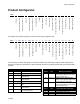
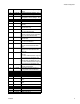
Product Configurator Product Configurator PR7F - - - - - - - - - - - - - I-J K L M N O P Q R S T U V Mixer Applicator Mounting Power Cord Flow Monitoring High Volume Side Tank High Volume Side Tank Cover Low Volume Side Tank Low Volume Side Tank Cover Tank Level Sensors Heat Zone Controller Off-Board Tank Stand G-H Dispense Valve F High Volume Side Hose High Volume Side Piston Air Motor D-E Low Volume Side Hose B-C Controls A Low Volume Side Piston Code: -
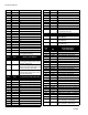
Product Configurator 4 5 6 7 8 9 A B C F G H J L M R S T U W X Y Z 140, Available in Nylon Only 160 180 200 220 240 260 280 300 320 360 400 440 480 520 560 600 640 720 800 880 960 Custom High Volume side, consult factory (stainless steel only) Code D Part A LC1___ B LC2___ C LC3___ Code E Part 1 2 3 4 5 6 7 8 9 A B C F G H 4 Low Volume Side Piston and Metering Tube Material Nylon Piston, Stainless Steel Metering Tube (last three digits of part number is the mm2 piston size) UHMWPE Piston, Stai
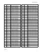
Product Configurator C3 LC0163 C4 LC0164 C5 LC0165 C6 LC0166 C7 LC0167 C8 LC0168 C9 LC0169 CA LC0170 CB LC0171 CC LC0172 CD LC0173 CE LC0174 D1 LC0175 D2 LC0176 D3 LC0177 D4 LC0178 D5 LC0179 D6 LC0180 D7 LC0181 D8 LC0182 D9 LC0183 DA LC0184 DB LC0185 DC LC0186 DD LC0187 DE LC0188 E1 LC0190 312394V Recirculating, On-Board Tanks, 3/16 in. (4.8 mm) - 15 ft (4.6 m) Recirculating, On-Board Tanks, 1/4 in. (6.5 mm) - 2.5 ft (0.
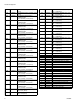
Product Configurator 6 GH LC0406 GJ LC0407 GK LC0432 GL LC0433 GM LC0434 GQ LC0435 GR LC0436 GS LC0437 GT LC0438 GU LC0439 GW LC0440 GX LC0441 GY LC0442 G1 LC0443 G2 LC0444 G3 LC0445 G4 LC0446 G5 LC0447 HA LC0472 HB LC0473 High Pressure, 3/4 in. (19 mm) - 10 ft (3.0 m) High Pressure, 3/4 in. (19 mm) - 15 ft (4.6 m) High Pressure, Recirculating, On-Board Tanks, 3/8 in. (9.5 mm) - 2.5 ft (0.6 m) High Pressure, Recirculating, On-Board Tanks, 3/8 in. (9.
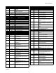
Product Configurator Code M Part Applicator Mounting Code P Part High Volume Side Tank N LC0294 1 LC0292 N 1 2 3 N/A 256896 255241 255250 2 3 LC0293 256439 4 255251 4 256438 None, Customer Mount Controls and Applicator Mast Mount, Controls & MD2 Applicator Machine Mounted Mast Mount, Controls Only Tank Stand Mount, Controls & MD2 Applicator Machine Mounted Tank Stand Mount, Controls Only 5 255281 Code N Part Power Cord Option 1 2 3 4 5 6 7 8 9 A B 121055 121054 121056 121057 121058
Product Configurator W X Y Z --- LC0129 8 L, Twin Polyethylene Tanks and Lids, Two 240V Agitators, with Shut-Off Valves LC0160 Accumulator, Fluoroelastomer LC0297 Accumulator, EP LC0237 7.5 L, Stainless Steel, High Level Sensors, 240V Heat When ordering tanks for spare or replacement parts, refer to Parts, page 27.
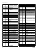
Product Configurator U LC0132 V W Z LC0142 LC0143 LC0146 Code T Part Tank Level Sensors N 2 N/A LC0278 3 LC0279 4 LC0282 5 LC0281 6 LC0280 7 LC0283 9 LC0284 A LC0287 B LC0286 C LC0289 D LC0285 E LC0288 G N/A None Polyethylene Tanks - Low Level Sensors Only Two 7.5 L Stainless Steel Tanks - Low Level Sensors Only Two 30 L or 60 L Stainless Steel Tanks - Low Level Sensors Only 7.
Warnings Warnings The following warnings are for the setup, use, grounding, maintenance, and repair of this equipment. The exclamation point symbol alerts you to a general warning and the hazard symbol refers to procedure-specific risk. Refer back to these warnings. Additional, product-specific warnings may be found throughout the body of this manual where applicable. WARNING ELECTRIC SHOCK HAZARD Improper grounding, setup, or usage of the system can cause electric shock.
Warnings WARNING FIRE AND EXPLOSION HAZARD Flammable fumes, such as solvent and paint fumes, in work area can ignite or explode. To help prevent fire and explosion: • Use equipment only in well ventilated area. • Eliminate all ignition sources; such as pilot lights, cigarettes, portable electric lamps, and plastic drop cloths (potential static arc). • Keep work area free of debris, including solvent, rags and gasoline.
Grounding Grounding Products that include electric agitators, heated hoses, or heated tanks must be grounded. In the event of an electrical short circuit, grounding reduces the risk of electric shock by providing an escape wire for the electric current. This product is equipped with a cord having a grounding wire with an appropriate grounding plug. The plug must be plugged into an outlet that is properly installed and grounded in accordance with all local codes and ordinances.
Installation Installation Polyethylene Tank Lid with Agitator 7. Attach appropriate hoses and cables. The polyethylene tank lid o-ring is installed with Krytox. Contact with Krytox can lead to flu-like symptoms. The MSDS for this material is available upon request. • For electric agitator models, plug the agitator power cable into one of the outlets in the incoming power bracket then turn on the power switch located on the agitator.
Installation Pneumatic Agitator Motor Level Sensors Polyethylene Tanks Always maintain a minimum of one inch clearance between rotating agitator parts and container to prevent sparks caused by contact. 1. Install sensor (2001) using two screws (2003). The cable (2002) for the sensor should be pointing towards the center of the machine base.
Installation Stainless Steel Tanks Accumulators The accumulator level sensors (144) can be installed on any side of the main cylinder (123). However, the sensor must be the specified distance from the pump flange. 2102 2101 2103 ti12494a 2104 CAUTION To prevent machine damage, if the material being cycled through the accumulator is moisture sensitive, a dryer must be installed in the air supply line before the accumulator. 1.
Installation Auto-Refill Installation The Auto-Refill assembly is shipped uninstalled. The Auto-Refill assembly can be installed in multiple places on the tanks. See FIG. 5. 1 1 ti12393a 1 Possible locations for Auto-Refill installation. FIG. 5: Auto-Refill Installation Locations Pressure Transducer and Flow Meter Installation See manual 312760.
Startup Startup 1. Locate power switch at rear of machine and turn power on. The display module will automatically turn on and begin to load. 2. Slide the system air pressure relief switch up. It is the yellow tab located at the rear, left of the machine. The hole in the tab should not be showing. 3. For systems with an Advanced Display Module: if the machine is in Disabled Mode, press the Select Operating Mode button ( ) repeatedly to exit Disabled mode and to select a new operating mode.
Pressure Relief Procedure Pressure Relief Procedure Models with Advanced Display Module Models with Standard Display Module 1. Place a waste container below the dispense valve. With the machine in an idle state: 2. Navigate to the Manual screen. 1. If the machine pistons are not fully retracted, retract 3. Press the Open Dispense Valve button on the Manual screen to relieve chemical pressure. the pistons by pressing in the M1 screen. See manual 3A0429 for more information. 2.
Setup Setup Level Sensor Calibration Stainless Steel Tanks Polyethylene Tanks 2102 2001 2101 2103 ti12494a 2002 2104 Teach Element 2003 ti12493b 1. Empty tanks by executing multiple shots. 2. Relieve pressure. See Pressure Relief Procedure, page 18. 3. With the level sensor installed, locate the “[OUT OFF]” button. Activate teach mode by holding the button down for at least two seconds but no more than six seconds. 4. The LED will flash once and then go out.
Setup Vacuum De-gas 10. Close bottom ball valve of the vacuum tree manifold (1015). 11. Turn off the vacuum pump. 12. Open the top ball valve of the vacuum tree manifold (1015). This procedure is for assemblies with Vacuum Tree Manifold and No Agitator or Auto-Refill. See FIG. 7. 1034 1015 CAUTION Operating the tank after the vacuum de-gas procedure without the top ball valve open will result in pump cavitation, off-ratio conditions, and possible collapse of the tank. 13.
Setup Vacuum De-gas and Vacuum Auto-Fill 12. If necessary, press the Abort/Cancel button ( to cancel auto-refill. This procedure is for assemblies with a Vacuum Tree Manifold, Agitator, and Auto-Refill. See FIG. 7 on page 20 for part references. 1. Press the Select Operating Mode button ( ) ) repeatedly to select Shot, Sequence, or Operator (Manual) mode. 2. Close the shut-off ball valves at the base of the tanks.
Setup Accumulator Filling 7. Use accumulator air pressure regulator (106) to adjust to desired accumulator air pressure. Accumulator air pressure should be set to the lowest possible setting to adequately run the accumulator. 106 8. See the PR70 and PR70v Operation manual referenced at the beginning of this manual to adjust display module run settings for the accumulator. 109 ti12561a 1. Relieve accumulator air pressure to zero using accumulator air pressure regulator (106). 2.
Shutdown Shutdown If the machine is to remain idle for an extended period of time, perform the following steps. 1. Place a waste container below the dispense valve. 2. If installed, remove static mixer from the end of the dispense valve. 3. Place a container below the dispense valve and activate a small shot to flush mixed material out of the valve. 4. Relieve pressure. See Pressure Relief Procedure on page 18. 5. With a clean rag and cotton swabs, clean the end of the dispense valve. 6.
Repair Repair Tank Removal 5. On models without ball valves, remove the tanks. 1. On models without ball valves, empty tanks by executing multiple shots. On models with ball valves, close the ball valves. • For polyethylene tank models, rotate the lock ring (218) for each tank counter clockwise and lift the tanks off of the base. 2. Relieve pressure. See Pressure Relief Procedure, page 18. • For stainless steel tank models, rotate the tank counter clockwise and lift the tank off of the base. 3.
Repair Stainless Steel Tanks 503 506a 3. Reassemble and install the four screws that hold the ball valve assembly together. Follow ball valve removal from tank procedure in reverse order. 505 506b 506c 506d 503 504 Assembly 255284 Shown ti12453a 1. Remove the stainless steel tanks from the base. 2. Remove four long screws (506d) holding the ball valve assembly together. 3. Remove three screws (505) holding the tank to the top plate of the ball valve assembly.
Repair Agitator Fuse Replacement 707 706 ti12559a 1. Slide open the fuse drawer (706). 2. Remove old fuse (707) and replace with new fuse.
Parts Parts Accumulators, Assemblies LC0160 and LC0297 126 1 128 Apply thread sealant tape to male npt threads prior to installation.
Parts Accumulators, continued 135 135 106 105 108 135 125 103 120 108 140 102 139 109 138 103 137 107 134 101 ti12472a 1 28 Apply thread sealant tape to male npt threads prior to installation.
Parts Ref 101 Part 15T679 102 01/1449/99 103 96/0282/98 104 84/1460-1/11 105 82/0053/11 106 82/0052/11 107 94/0070/96 108 94/0642/96 109 94/0809/96 110 15T686 111 01/1454/98 112 121307 113 94/0616/98A 114 94/0360-2/98 115 116 94/0348/11 95/0223/02 95/0223/00 117 120904 118 119 15M849 96/0304-4/98 120 94/3201/96 121 94/0545/98 122 123 01/1453/99 01/1455/98 124 01/1451/98 125 94/0702/96 126 01/1456/97 312394V Description Qty COVER, front, accumulator, 1 mild ste
Parts 8 Liter Polyethylene Tanks CAUTION The electric agitators used with on-board tanks will fail prematurely when material viscosity exceeds 24,000 cps. Use pneumatic agitators if material viscosity exceeds 24,000 cps. 216 209 220 210 2 202 2 215 203 218 207 219 2 2 201 223 213 212 217 201 204 214 222 205 221 206 208 224 Assembly 255282 Shown 30 211 1 Apply thread sealant tape to male npt threads prior to installation. 2 Do not attempt to remove from tank.
Parts †* 255281, Tank with Ball Valves Part 255241, Tank Ref 201 2 4 4 4 2 2 2 2 4 4 2 2 4 4 O-RING SCREW, button head cap screw, M5 x 0.8 x 40 mm SCREW, socket head cap, M5 x 0.8 x 18 mm NUT, HEX, lock M5 X 0.8 NUT, HEX, lock M8 X 1.
Parts Polyethylene Tank Agitators Electric Agitator Assemblies 255246 and 255503 701 1 Shown for reference only.
Parts Ref 701 703 704 705 706 707 708 709 710 711 712 713 714 715 716 717 718 719 720 721 723 724 725 726 Part 01/2218/97 01/2219/97 81/2218-1/11 Description Qty ENCLOSURE, agitator, electric, prmv/f, hd 1 PLATE, adapter, electric agitator, hd, prm 1 MOTOR, 50 rpm, 60 in-lb, 120V, 1.
Parts Pneumatic Agitator Assembly 255730 801 1 1 802 808 2 813 817 823 805 815 816 818 809 824 818 810 804, 811 821 807 806 817 815 814 816 822 812 819 1 Apply thread sealant tape to male npt threads prior to installation. 2 Shown for reference only.
Parts Ref 801 802 Part 82/0216/11 94/0838/96 804 805 806 01/1189/98 5-01-0510 84/2215-A/11 807 808 809 84/2215-B/11 94/0702/96 95/0842/11 810 811 95/0864/00 96/0029/99 812 813 814 815 816 96/0817/99 120904 120905 120907 120928 817 818 120930 121173 819 821 822 823 824 255724 15K884 15K886 15R363 15R364 312394V Description MOTOR, motor, pneumatic, agitator, 0.32 hp VALVE, needle, 1/8 npt x 1/8 npt, male / female ADAPTER, coupling, air motor, agitator SCREW, socket head cap, 10-32 x 5/8 in.
Parts Agitator Shaft, 255724 906 905 907 902 901 905 901 903 904 ti12458a Ref 901 902 903 Part 01/2230-1/98 01/2230-2/98 96/0097/98 904 96/0125/98 905 96/0129/98 906 907 96/0304-4/98 15R307 36 Description Qty PADDLE, agitator, tfm tank, stainless steel 2 SUPPORT, mount, paddle, agitator 1 FASTENER, screw, socket head cap, 10-24 2 x 1.25, stainless steel FASTENER, screw, socket head cap, 1 10-24 x 0.50, stainless steel WASHER, flat, SAE, #10, stainless steel, 4 1/2 in. OD, 0.
Parts On-Board Stainless Steel Tanks Tank Assemblies LC0237, LC0238, LC0254, and LC0255 Right hand tank shown, left hand tank is mirror image. 3 2 304 304a 302 306 4 309 301 Assembly LC0237 Shown 307 303 312394V 308 1 305 1 4 ti12451a 4 1 Use glass cloth tape to secure ground strap, thermal switch, and RTD to tank wall before adding heat blanket. 2 Secure heat blanket to tank with string laced through eyelets. 3 Insulation blanket should cover heat blanket completely.
Parts Ref 301 Part --- 302 303 304 304a 305 306 307 308 309 LC0861 256558 LC0056 121208 256611 121615 121478 256612 121682 310 † 121633 Description Qty Refer to Tanks for Use with Dust Covers and 1 Tanks for Use with Clampdown Covers, page 44, for replacement or spare parts. BLANKET, heat, 7.5L tank, 220V 1 SWITCH, assy, thermal, 125C, 3P, M8 1 BLANKET, insulation 1 LABEL, hot surface SENSOR, assy, 1.5 in.
Parts Tank Assemblies 255284, 255285, LC0235, LC0236, LC0012, and LC0013 It is recommended that the flat face of the tank faces the back of the base machine. Right hand tank shown, left hand tank is mirror image.
Parts Ball Valve, Assembly 255280 2204a 2204b 2204c 2202 2201 2204h 2203 2204j 2205 2204d 2206 2204e 2204f ti12564a 2204g Ref 2201 2202 2203 Part 96/0075-1/99 96/0075/99 121012 2204 121111 2205 15M224 2206 15M225 40 Description Qty WASHER, flat, sae, 7/16, mild steel, n series 1 WASHER, lock, split, 7/16, mild steel 1 SCREW, M8 x 1.25 65 mm, socket head cap 4 screw, stainless steel VALVE, ball, 3 piece, 1-1/4 in.
Parts Flange Assembly, 256896 The flange assembly can be installed if no tanks or accumulators are installed. It allows for other feed system options to be installed onto the pump subassembly. 2701 ti12455a Ref 2701 2702 2703 * Part Description Qty 15M237 Flange, 1-1/2 in. npt 1 * 95/0223/00 O-RING, fluoroelastomer, bbc 1 * 120904 SCREW, socket head cap, M5 3 x 0.8 x 18 mm Part not shown.
Parts On-Board Stainless Steel Tank Lids Lid Assemblies LC0019 to LC0026 and LC0130 to LC0132 CAUTION The electric agitators used with on-board tanks will fail prematurely when material viscosity exceeds 24,000 cps. Use pneumatic agitators if material viscosity exceeds 24,000 cps. 1017 Assembly LC0025 Shown 1018 1019 1027 1020 1028 1021 1015 1023 1008 1021 1034 1024 1009 1006 1 1007 1033 1025 1016 1026 1030 1029 1016 1016 1035 1011 1010 1022 1005 (Tank shown for reference only.
Parts Description Reference Only. Tank sold separately.‡ O-RING, fluoroelastomer, JJF FASTENER, screw, button head cap screw, 8-32 x 0.
Parts Tanks for Use with Dust Covers LC0012 7.5 L stainless steel LC0235 7.5 L stainless steel with high level port LC0013 3 L stainless steel Tanks for Use with Clampdown Covers 24U714 7.5 L stainless steel with clamps 24U713 7.5 L stainless steel with high level port and clamps 24U715 3 L stainless steel with clamps Ball valve shutoff assemblies and mounting hardware must be ordered separately.
Parts Lid Assembly LC0018 1303 1301 1304 1302 ti12461a 1 Ref Part 1301 15M956 1302 96/0127/98 1303 96/0148/11 1304 96/0311/98 312394V Apply thread sealant tape to male npt threads prior to installation. Description Qty LID, mod, 7.5L & 3L, stainless steel 1 FASTENER, socket head cap screw, 1/4-20 x 1 0.
Parts Off-Board Stainless Steel Tanks Tank Assemblies LC0054 and LC0055 601 1 606 601 1 1 601 602 1 Apply thread sealant tape to male npt threads prior to installation. 605 1 603 604 ti12454a Assembly LC0054 Shown Ref 601 602 603 604 605 606 Part 111384 103778 108832 120904 255391 † Description Qty PLUG, pipe 5 PLUG, pipe, headless 1 O-RING 1 SCREW, socket head cap, M5 x 0.8 x 18 mm 3 SYSTEM, pipe and tube, 1-1/2 in.
Parts Tank Assemblies LC0259 and LC0260 408 403 3 5 2 407 402 401 404 1 5 406 1 405 Assembly LC0259 Shown 312394V 4 ti12452a 1 Use glass cloth tape to secure ground strap, thermal switch, and RTD to tank wall before adding heat blanket. 2 Secure heat blanket to tank with string laced through eyelets. 3 Insulation blanket should cover heat blanket completely. Secure insulation blanket to tank with 2 in. wide velcro strap.
Parts Pipe and Tube System, 255391 Ref 401 Description Qty TANK, assy, 30 L, stainless steel 1 (assembly LC0259 only) LC0055 TANK, assembly, 60 L, stainless steel (assembly LC0260 only) 402 LC0257 BLANKET, assy, heat, 30L, 240V, 1 GCA (assembly LC0259 only) LC0258 BLANKET, assy, heat, 60L, 240V, GCA (assembly LC0260 only) 403 257757 INSULATOR, blanket assy, 38 L 1 (assembly LC0259 only) 257758 INSULATOR, blanket assy, 75 L (assembly LC0260 only) 403a 1 121208 LABEL, hot surface 404 257759 SENSOR, thermowe
Parts Off-Board Stainless Steel Tank Lids Lid Assembly LC0101 1101 1103 1105 1102 1102 1101 ti14656a 1 Ref 1101 1102 1103 1104 1105 Part 111384 122767 94/0736/96 15M578 15R145 312394V 1104 Apply thread sealant tape to all pipe threads.
Parts Lid Assembly LC0102 1204 1202 1207 1203 1205 1206 1201 ti14722a 1202 1 Ref 1201 1202 1203 Description GAUGE, pressure, fluid BUSHING, 1/2 npt x 1/4 npt, stainless steel FITTING, reducer, pipe, 3/4 x 1/4, stainless steel 1204 94/0736/96 VALVE, drain cock, 1/4 npt, male, brass 1205 257746 FITTING, vacuum tree 1206 15M578 LID 1207 15R145 VALVE, relief, 1/4 npt, male, 40 psi, sil 50 Part 187875 122767 15M861 Apply thread sealant tape to male npt threads prior to installation.
Parts 312394V 51
Parts Lid Assemblies LC0050, LC0144, LC0145, LC0146, LC0147 CAUTION The electric agitators used with off-board tanks will fail prematurely when material viscosity exceeds 48,000 cps. Use pneumatic agitators if material viscosity exceeds 48,000 cps. 1401 Assembly LC0147 Shown 1406 1408 1403 1405 1407 1409 1404 1402 1411 1410 ti12460b 1 52 Apply thread sealant tape to male npt threads prior to installation.
Parts Quantity Ref Part 1401 24J183 256822 1402 1403 15M621 122776 1404 257607 257608 1405 122767 1406 15R145 1407 1408 1409 187875 257746 257602 1410 1411 111384 255747 257606 Description AGITATOR MOTOR, single phase, 50/60 hz LID, agitator RING, retaining, external, 0.
Parts Lid Assemblies LC0042, LC0043, LC0142, and LC0143 CAUTION The electric agitators used with off-board tanks will fail prematurely when material viscosity exceeds 48,000 cps. Use pneumatic agitators if material viscosity exceeds 48,000 cps. 1504 1503 1505 1501 1508 1507 1506 1506 1502 ti12464b Assembly LC0143 Shown 1 54 Apply thread sealant tape to male npt threads prior to installation.
Parts Quantity Ref 1501 1502 1503 Part 255607 255608 15M621 15M578 122776 1504 24J183 1505 187875 15M861 111384 1506 122767 1507 94/0736/96 1508 15R145 1509 † 255746 Description BLADE, assy, agitator BLADE, assy, agitator LID LID RING, retaining, external, 0.
Parts Lid Assemblies LC0047, LC0048, LC0051, LC0052 CAUTION The electric agitators used with off-board tanks will fail prematurely when material viscosity exceeds 48,000 cps. Use pneumatic agitators if material viscosity exceeds 48,000 cps. 1602 1608 1605 1606 1604 1609 1607 1603 1601 1611 1610 1607 Assembly LC0051 Shown ti17647a 1 56 Apply thread sealant tape to male npt threads prior to installation.
Parts Quantity Ref Part Description LC0047, LID, assy, 7.5 gal, agit LC0051, LID, assy, LC0048, 7.
Parts Vacuum Tree Manifold, 255342 Vacuum Tree Manifold, 257746 3004 2901 2902 2904 2905 3003 3002 3001 2903 2902 ti12576a ti12575a 1 Apply thread sealant tape to male npt threads prior to installation. Ref Part 2901 82/0220-1/11 Description Qty GAUGE, 30 in. hg, 30 psi, 1 liquid filled 2902 94/0900-R2/99 VALVE, ball, 2-way, 1/4 npt, 2 female, 2K, mild steel 2903 121087 FITTING, tee, 1 male-male-male, 1/4 in. NPT 1 2904 121088 FITTING, tee, male-male-female, 1/4 in.
Parts 312394V 59
Parts Stainless Steel Tank Agitators Electric Agitator Motor Assembly, 256822 1705 1707 1706 1701h 1701a 1701j 1701k 1701i 1701f 1701j 1701b 1701g 1701z 1701af 1701l 1701m 1701n 1701z 1701e, 1701t 1701v, 1701w, 1701ab, 1701ac, 1701ad, 1701ae, 1702, 1701r, 1701s 1701o 1701c, 1701d 1701p 1701q 1703, 1701x, 1701y, 1701aa 1704 1701u 1701ag ti17646a 60 312394V
Parts Ref 1701 . 1701a . 1701b Part 257605 124741 16K267 . 1701c . 1701d . 1701e . 1701f . 1701g . 1701h . 1701i . 1701j . 1701k . 1701l . 1701m . 1701n . 1701o . 1701p .
Parts Electric Agitator Motor, Assemblies 255337 and 255338 2507 2508 2506 2511 2501 2513 2502 2509 2505 ti12584a 2503 2512 2504 2511 Assembly 255337 Shown Ref 2501 2502 2504 2505 Part 01/1198-2/97 01/2218/97 01/2219/97 81/2218-1/11 Description Qty FASTENER, standoff, agitator, hd, elec, alu 4 ENCLOSURE, agitator, electric, prmv/f, hd 1 PLATE, adapter, electric agitator, hd, prm 1 MOTOR, 50 rpm, 60 in-lb, 120V, 1.
Parts Pneumatic Agitator Motor Assembly, 02/1116/50 2605 2604 2601 2602 2606 2603 ti12585a Ref 2601 2602 2603 Part 82/0216/11 01/1189/98 01/1168/98 2604 94/0838/96 2605 94/0702/96 2606 01/1179/98 312394V Description MOTOR, pneumatic, agitator, 0.
Parts Pneumatic Agitator Motor, 255670 Pneumatic Agitator Motor, 24J183 NOTE: This agitator assembly is no longer available. Piece parts from the assembly can be ordered but if the entire assembly is needed then agitator kit 24J182 must be ordered.
Parts Agitator Blade Assemblies 257607 and 257608 1902 1901 ti12468a Assembly 257607 Shown 1901c 1901b 1901b 1901a 1901c 1901d ti12474a Ref Part 1901 257604 1901a 15Y362 1901b 15Y361 1901c 551903 1901d 122778 1902 15M624 15M625 312394V Description BLADE, assy, electric agitator BLOCK, blade, coupler, 1 in. diameter BLADE, agitator FASTENER, socket head cap screw, 1/4-20 x 0.50, stainless steel FASTENER, square head, 1/4-20 x 0.
Parts Level Sensors Polyethylene Tanks Level Sensors, Assembly LC0278 2002 2001 ti12470b 2003 Ref Part 2001 123549 2002 121686 2003 96/1000/99 66 Description Qty SENSOR, level, quick disconnect 2 CABLE, M8 x M8, 4P, female / male, 2 straight/right angle, 2 m FASTENER, screw, socket head cap, 4 M3 x 8, mild steel 312394V
Parts Stainless Steel Tanks Level Sensors 2103 2102 2101 2104 ti12469a Reference Number, Description, Quantity 2101 Sensor Package LC0279 LC0280 LC0281 LC0282 LC0283 LC0284 LC0285 LC0286 LC0287 LC0288 LC0289 312394V 2102 2103 121511 01/0025-EF/87 15U978 Description Level Sensor Level Sensor Well Sensor Well Cap Low level sensor for two 7.5 L tanks 2 2 2 Low level sensor for one 7.5 L tank 1 1 1 Low level sensor for one 7.
Kits Kits Mixer and Shroud Options Part LC0063 LC0057 LC0058 LC0059 LC0060 LC0061 LC0062 LC0077 LC0078 LC0079 LC0080 LC0081 LC0083 LC0082 LC0084 LC0085 LC0086 LC0087 LC0088 LC0089 LC0090 Description Mixer, 3/16 in. (6.5 mm) x 32, 10 Mixers with shroud Mixer, 1/4 in. (6.5 mm) x 24, 10 Mixers with shroud Mixer, 3/8 in. (9.8 mm) x 24, 10 Mixers with shroud Mixer, 3/8 in. (9.8 mm) x 36, 10 Mixers with shroud Mixer, 3/8 in. (9.8 mm) Combo, 10 Mixers with shroud Mixer, 3/16 in. (4.
Kits Vacuum Kits Refill Kits These vacuum kits contain the parts necessary to attach a vacuum pump to the tanks. Refill Kits 256659 and 256660 are designed to turn on and off a transfer pump as needed to keep the tanks at the proper fluid level. Tank Refill Kit 256577 is designed to open and close a valve to allow fluid to flow into the tank from an always-on transfer pump. Tank Refill Kit 256577 includes the parts necessary to install on the base or lid of a 7.5 L, 30 L, or 60 L tank.
Dimensions Dimensions Machine with On-Board Tanks A D ti12621b ti12622b C B PR70 † Assembly Dimensions, in. (mm) Stainless Steel Tanks Polyethylene Tanks Ref A B C D No Agitators With Agitators 3L 7.5 L, No Agitators 7.5 L, with Agitators 26.4 (670) 18.5 (470) 30.6 (778) 13.4 (340) 38.6 (980) 18.5 (470) 30.6 (778) 13.4 (340) 28.2 (716) 15.5 (394) 30.6 (778) 13.4 (340) 38.2 (970) 15.5 (394) 30.6 (778) 13.4 (340) 39.9 (1013) 15.5 (394) 30.6 (778) 13.4 (340) PR70v † Assembly Dimensions, in.
Dimensions Machine with Off-Board Tanks A D ti12624c ti12623c C B PR70 † Assembly Dimensions, in. (mm) 30 L Tank Ref A B C D 60 L Tank No Agitators With Agitators No Agitators With Agitators 55.7 (1415) 32.1 (815) 29.3 (236) 16.0 (406) 83.4 (2118) 32.1 (815) 29.3 (236) 16.0 (406) 64.9 (1648) 32.1 (815) 29.3 (236) 16.0 (406) 89.5 (2273) 32.1 (815) 29.3 (236) 16.0 (406) PR70v † Assembly Dimensions, in.
Technical Data Technical Data Metering Pump Effective Area . . . . . . . . . . . . . . . . . . . . . 80 to 960 mm2 (0.124 to 1.49 in.2) per side Small Air Cylinder Effective Area . . . . . . . . . . . . . . . . . . . 4560 mm2 (7.07 in.2) Large Air Cylinder Effective Area . . . . . . . . . . . . . . . . . . 10260 mm2 (15.9 in.2) Maximum Stroke Length . . . . . . . . . . . . . . . . . . . . . . . . . 38.1 mm (1.50 in.) Minimum Stroke Length . . . . . . . . . . . . . . . . . . . . . . . . . 5.8 mm (0.23 in.
Graco Standard Warranty Graco Standard Warranty Graco warrants all equipment referenced in this document which is manufactured by Graco and bearing its name to be free from defects in material and workmanship on the date of sale to the original purchaser for use. With the exception of any special, extended, or limited warranty published by Graco, Graco will, for a period of twelve months from the date of sale, repair or replace any part of the equipment determined by Graco to be defective.