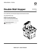
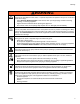
Instructions - Parts Double Wall Hopper For use with XM™ plural-component sprayers and immersion heaters. For professional use only. 255963, Double Wall Hopper 20 Gallon (75 liter) Spray Material Fluid Capacity 12 Gallon (45 liter) Heated Material Fluid Capacity See page 12 for optional accessories and approvals. Important Safety Instructions Read all warnings and instructions in this manual. Save these instructions.
Related Manuals Contents Related Manuals . . . . . . . . . . . . . . . . . . . . . . . . . . . 2 Optional Accessories . . . . . . . . . . . . . . . . . . . . . . . 3 Warnings . . . . . . . . . . . . . . . . . . . . . . . . . . . . . . . . . 4 Keep Components A and B Separate . . . . . . . . . 6 Changing Materials . . . . . . . . . . . . . . . . . . . . . . . 6 Component Identification . . . . . . . . . . . . . . . . . . . . 7 Double Wall Hoppers Mounted on Side of Frame 7 Overview . . . . . . . . . . . . .
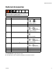
Optional Accessories Optional Accessories Not all accessories and kits are approved for use in hazardous locations. Refer to the specific accessory and kit manuals for approval details. Part 256257 Description Approvals 240V 1 PH Immersion Heater C US 207901 (For heater 121376.) 256512 Desiccant Kit 256274 Agitator Kit N/A 0359 II 1/2 G T3 ITS03ATEX11226 (For agitator 224854.) 256275 T2 2:1 Ratio Transfer Pump Kit (For pump 295616.
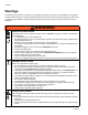
Warnings Warnings The following warnings are for the setup, use, grounding, maintenance, and repair of this equipment. The exclamation point symbol alerts you to a general warning and the hazard symbol refers to procedure-specific risk. Refer back to these warnings. Additional, product-specific warnings may be found throughout the body of this manual where applicable. WARNING WARNING FIRE AND EXPLOSION HAZARD Flammable fumes, such as solvent and paint fumes, in work area can ignite or explode.
Warnings WARNING WARNING PRESSURIZED EQUIPMENT HAZARD Fluid from the gun/dispense valve, leaks, or ruptured components can splash in the eyes or on skin and cause serious injury. • Follow Pressure Relief Procedure in this manual, when you stop spraying and before cleaning, checking, or servicing equipment. • Tighten all fluid connections before operating the equipment. • Check hoses, tubes, and couplings daily. Replace worn or damaged parts immediately.
Warnings Keep Components A and B Separate NOTICE To prevent cross-contamination of the equipment’s wetted parts, never interchange component A and component B. Changing Materials • When changing materials, flush the equipment multiple times to ensure it is thoroughly clean. • Check with your material manufacturer for chemical compatibility. • Some materials use catalyst on the A side, but some applications may use catalyst on the B side.
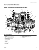
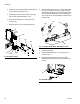
Component Identification Component Identification Double Wall Hoppers Mounted on Side of Frame R H A C H J J G D K D N P L E M B M E F FIG.
Overview Overview Double wall hoppers (D) can be mounted on the back or side of the frame (A) to gravity feed spray material to the Xtreme lower (B). Feed pumps (H) and agitators (J) can be mounted on top of the hoppers to pressure feed spray material directly to the pump. XM sprayers are not approved for use in hazardous locations unless the base model, all accessories, all kits, and all wiring meet local, state, and national codes. A strainer inside the hopper (D) prevents objects larger than 1/4 in.
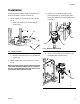
Installation Installation Hopper mounting kit 256259 allows the hoppers (D) to mount on the sides or back of the frame (A). 1. Mount hoppers (D) on sides of the frame (A). See FIG. 3. a. Remove four screws (306) holding solvent pump bracket (307) to mounting plate (308). Leave pump attached to bracket. Remove pump and bracket. a. Attach main bracket (101) to frame (A) with screws (107). A 101 308 306 307 107 FIG. 4: Remove Solvent Pump FIG. 3: Sides of Frame b. b.
Installation c. Attach the corner bracket (103) to frame (A) with screws (108) and washers (110). d. Attach lower mount bracket (104) to frame (A) with screws (108) and washers (110). 3. Connect reducing swivel (211) to fluid outlet assembly (F) if your system uses a 50:1 pump. Connect reducer bushing fitting (212) and swivel fitting (215) to fluid outlet assembly (201) if your system uses a 70:1 pump. Do not use pipe sealant on swivel end of swivel fittings. e.
Installation 7. Align holes on main bracket (101) and thread inserts of the hopper (D). Loosely fasten hopper (D) to bracket (101) with four screws (107) and washers (110). 9. Tighten union (208) and ensure fluid outlet assembly is aligned. See FIG. 7 on page 10. 10. Tighten hopper mounting screws (107). See FIG. 9. 11. Install screws (107) and bottom support (109). D 107 101 D 110 107 107 109 FIG. 9: Attach Hopper to Bracket 8. Connect swivel fitting (202) to nipple (201). FIG.
Installation Optional Accessories 4. Install bushing (302) in top of wiring outlet. Route power cable (303) through bushing (302). See Accessories page 28 for a list of all accessories that can be used with double wall hoppers. D 302 Immersion Heater Kit 256257 The immersion heater (L) is only approved for non-explosive atmosphere applications. Using the immersion heater in hazardous locations, or explosive atmospheres, may cause ignition or explosion.
Installation 8. Set thermostat knob (TK) to desired spray material conditioning temperature. Align temperature setting to set point (SP). NOTE: Set point (SP) is a “V” notch in the metal bracket at the top of the thermostat dial. Maximum setting is 140°F (60°C). 303 SP TK BA BB 302 L HC 303 FIG. 14: Connect Immersion Heater FIG. 15: Immersion Heater Power Cables 9. Install immersion heater cover (HC) with screws (HS). See FIG. 13. 11.
Setup Setup 1. Remove the large A or B label from the label sheet (24) and apply to front face of the appropriate hopper to help avoid filling the wrong materials and causing cross-contamination. 3. Connect other end of recirculation hose to recirculation valve (V) on XM sprayer. R 24 R V FIG. 16: Apply Label 2. Remove the small A or B from the label sheet (24) and apply on lid. FIG. 18: Recirculation Hose and Recirculation Valve 4. Repeat for second hopper.
Setup Fill Heating Fluid Fill the hopper’s outer jacketed area with oil or a 50% water and 50% ethylene glycol mixture to heat your spray material. The double wall hopper design prevents the spray material from losing heat during downtime and overnight. NOTICE Algae can form inside the outer jacketed area if you are using only water to heat your spray material. Always add ethylene glycol to the water to prevent the formation of algae.
Setup Fill Spray Material Left Side Shown Condition materials prior to adding to hoppers. Ensure resin materials are thoroughly agitated, homogenous, and pourable prior to adding to hopper. Stir hardeners back into suspension prior to adding material to hopper. (45°) 1. Disconnect spring strap (7) from front post and remove lid (1c). Keep connected to lanyard (10). 10 Open Port 7 FIG. 21: Orientation of Venting Fittings 5. Install plug (6) in opposite port and torque to 20-30 ft-lbs (27-41 N•m).
Operation Operation Startup Flush Hopper 1. Ensure that the outer jacketed area is filled with water mixture or oil and the accessories are correctly installed. 1. Drain Spray Material. See page 19. 2. Follow Setup procedure in manual 312359. 3. See manual 312359 for testing material and operation instructions before spraying material. 2. Flush hoppers and fluid inlet assemblies (F) with compatible solvent before switching materials or cleaning hopper (D). See Flushing section in manual 312359. 3.
Maintenance Maintenance Drain Heating Fluid 1. Turn off all heaters and allow heating fluid to cool for a minimum of 8 hours. Check Heating Fluid Level Gradual fluid evaporation can occur, therefore, check the level of heating fluid monthly. 1. Remove plug (6). 2. Place either a 1-gallon (4-liter) or 3-gallon (7-liter) pail directly beneath drain plug (37). NOTE: Only 1-gallon (4-liter) pails fit beneath drain plug if hoppers are mounted on the back of the frame. 2.
Maintenance Drain Spray Material 206 1. Flush and Shutdown XM sprayer. See XM operation manual. 2. Turn off all fluid heaters (S) and allow heating fluid to cool for a minimum of 8 hours. 3. Place a clean 1 gallon (4 liter) pail directly beneath union (208) and ball valve (206). FIG. 27: Drain Hopper 4. Close ball valve (206) and open union (208) with wrench. 8. Use additional pails as necessary until all material is drained. 9. Close ball valve (206) and use two wrenches to retighten union (208).
Repair Repair Remove Immersion Heater 1. Turn off power to system. See the XM Operation manual. 2. Drain Heating Fluid. See page 18. Remove Fluid Outlet Assembly Kit 1. Drain Spray Material. See page 19. 2. Loosen fitting (212) or (211). 3. Remove screws (HS) and immersion heater cover (HC). 303 3. Loosen fitting (202). 4. See Installation on page 9 for assembly instructions. 302 211 215 212 201 202 206 HS HC FIG. 28: Connect Immersion Heater 208 FIG. 29: Fluid Outlet Assembly 4.
Repair Remove Hopper Replace Gaskets 1. Check Heating Fluid Level. See page 18. The following procedure applies to both the hopper gaskets (13) and hopper lid gasket (12). 2. Drain Spray Material. See page 19. 3. Disconnect swivel fitting (202). See FIG. 29. 1. Remove old gasket and residual adhesive using MEK solvent. 4. If a transfer pump (H) or agitator (J) is mounted to the hopper: 2. Clean groove in hopper using isopropyl alcohol. Let air dry. a. Relieve pressure. See manual 312769. b.
Troubleshooting Troubleshooting Problem Cause Lid does not properly seal on hopper. Material build up. Damaged gasket. Solution Remove built up material from gasket. Replace as necessary. Material leaking between cover and hopper. Gasket is not sealed properly. Check for built up material on gasket. Replace as necessary. Algae in water. Ethylene glycol was not added to water. Drain fluid. Add 50/50 water and ethylene glycol mixture in outer cavity Immersion heater no longer heating.
Troubleshooting 312747L 23
Parts Parts 255963, Double Wall Hopper 9 1 Assemble with lips facing down. 2 Torque to 20-30 ft-lbs. 3 Clean groove with isopropyl alcohol before applying gasket adhesive to plastic. Cut to length.
Parts 255963, Double Wall Hopper Ref. 1a 1b 1c 4 5 6 7 8 9 Part 10 11 12 13 14 19 122097 256008 15T010 15T011 15R403 112547 24 15R424 26 28 32 121378 121485 121797 33 34 35 36 189285 15R331 104105 117326 37 39 100737 158683 40† 24K965 255965 15T007 121621 255966 109570 513764 Description Qty HOPPER 1 COVER 1 LID 1 PLATE, weldment 2 ADAPTER, return tube 4 PLUG, 3/4 in. npt 3 STRAP, spring, hopper lid 1 WASHER, plain; 1/2 in. 2 SCREW, cap, socket head; 1 1/2-13 x 0.
Parts 256259, Double Wall Hopper Mounting Kit Back Mounted Double Wall Hopper Side Mounted Double Wall Hopper 108 110 103 101 107 101 107 107 109 107 110 108 107 104 109 Ref. 101 103 104 107 108 109 110 26 107 Part No. Description Qty. 256224 BRACKET, hopper, 20-gallon 1 256254 BRACKET, hopper, wldmt, bottom 1 mount 256256 BRACKET, hopper, bottom mount, 1 lower 112395 SCREW, cap, flng hd; 3/8-16 x 0.75 14 121488 SCREW, hex hd, flanged; 4 3/8-16 x 2.
Parts 256170, Universal Hopper Fluid Outlet Kit 201 202 215 211 212 217 203 205 216 207 204 206 208 207 210 Ref. 201 202 203 204 205 206 207 208 209 210 211* 212† 215† 216 217 * 209 Part No. 121435 121436 121437 121438 121439 121440 121441 121442 121443 101496 121445 121446 121447 104663 123807 Description NIPPLE, hex; 2 in. FITTING, swivel, male; 2 in. FITTING, tee, female; 2 in. BUSHING, reducer; 2 x 1 1/2 in.
Accessories Accessories 262820, Flexible Fluid Connection Kit 256512, Desiccant Kit For gravity feeding from 20 gallon hopper to proportioner with Xtreme lower. For removing moisture in replacement air for moisture-sensitive spray materials. See manual 406739 for parts list.
Technical Data Technical Data 20 Gallon Heated Compatible Hopper 256233 Maximum (continuous) temperature rating. . . . . . . . . . . . Maximum pressure rating (outer cavity) . . . . . . . . . . . . . . Inner Tank Capacity (spray material) . . . . . . . . . . . . . . . . Outer Jacketed Area Capacity (heating fluid) . . . . . . . . . . Outlet Port . . . . . . . . . . . . . . . . . . . . . . . . . . . . . . . . . . . . Hopper Material . . . . . . . . . . . . . . . . . . . . . . . . . . . . . . . .
Technical Data Hopper Stand Hopper on Stand 36 in. (914 mm) 14.5 in. (368 mm) 1.5 in. (38 mm) 75.4 in. (1915 mm) 26.5 in. (673 mm) 1.5 in. (38 mm) 42.3 in. (1074 mm) 17.5 in.
Technical Data 312747L 31
Graco Standard Warranty Graco warrants all equipment referenced in this document which is manufactured by Graco and bearing its name to be free from defects in material and workmanship on the date of sale to the original purchaser for use. With the exception of any special, extended, or limited warranty published by Graco, Graco will, for a period of twelve months from the date of sale, repair or replace any part of the equipment determined by Graco to be defective.