Operation - Parts S-Head For dispensing Polyol and Isocyanate. 3000 psi (20.68 MPa, 206.8 bar) Maximum Working Pressure Important Safety Instructions Read all warnings and instructions in this manual. Save these instructions.
Models Contents Models . . . . . . . . . . . . . . . . . . . . . . . . . . . . . . . . . . . Warnings . . . . . . . . . . . . . . . . . . . . . . . . . . . . . . . . . Isocyanate Hazard . . . . . . . . . . . . . . . . . . . . . . . . . . Material Self-ignition . . . . . . . . . . . . . . . . . . . . . . . . Moisture Sensitivity of Isocyanates . . . . . . . . . . . . Keep Components A and B Separate . . . . . . . . . . Foam Resins with 245 fa Blowing Agents . . . . . . . Changing Materials . . . . . . . . .
Warnings Warnings The following warnings are for the setup, use, grounding, maintenance, and repair of this equipment. The exclamation point symbol alerts you to a general warning and the hazard symbol refers to procedure-specific risk. Refer back to these warnings. Additional, product-specific warnings may be found throughout the body of this manual where applicable.
Warnings WARNING EQUIPMENT MISUSE HAZARD Misuse can cause death or serious injury. • Do not operate the unit when fatigued or under the influence of drugs or alcohol. • Do not exceed the maximum working pressure or temperature rating of the lowest rated system component. See Technical Data in all equipment manuals. • Use fluids and solvents that are compatible with equipment wetted parts. See Technical Data in all equipment manuals. Read fluid and solvent manufacturer’s warnings.
Isocyanate Hazard Isocyanate Hazard Spraying materials containing isocyanates creates potentially harmful mists, vapors, and atomized particulates. • Keep the ISO lube pump reservoir filled with Graco Throat Seal Liquid (TSL), Part 206995. The lubricant creates a barrier between the ISO and the atmosphere. • Use moisture-proof hoses specifically designed for ISO, such as those supplied with your system. • Never use reclaimed solvents, which may contain moisture.
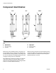
Component Identification Component Identification LEFT D RIGHT TOP E B C F A G G H FIG. 1 Key: A B C D Hydraulic-open Hydraulic-close Isocyanate supply Iso-return Within each nozzle assembly, there is an injection nozzle and needle valve kit (101) where the chemicals are introduced into the mixing chamber. In the mixing chamber, the two chemicals are impinged against each other causing the mixing of the two components.
Installation Installation Mounting Use the bolt pattern provided on the front face of the gun block for mounting. Never use any of the assembly bolts for mounting purposes. AA AE AB AD AC FIG. 2 Key: AA AB AC AD AE 5.096 in. (129.44 mm) 2.7550 in. (69.98 mm) 1.9360 in. (49.17 mm) 3/8-16 x 0.875 in. deep 1.9360 in. (49.
Operation Operation 4. Tighten the hex locknut (103) against the injection nozzle retainer (102). This will lock the injection adjustment screw position. Do not come into contact with Isocyanate. See Isocyanate Hazard on page 5. 1. Ensure that a nozzle assembly with appropriate size orifice is installed. See Orifice Size Selection section on page 13. CAUTION Do not over-adjust the injection adjustment screw and close the needle valve into the orifice of the needle housing.
Maintenance Maintenance When using MixHead, be careful to avoid damaging precision tip. Return MixHead to Graco once a year for maintenance. Nozzle Assembly b. Holding on to 1/4-20 bolt, pull needle (206) out rear of needle housing (205). See FIG. 4 on page 12. 5. Use an o-ring pick to remove o-rings. CAUTION DO NOT soak the o-ring in cleaning solvents as they will swell and be unusable. Shut off all power. Bleed the chemical, hydraulic, and tank pressures to zero pressure.
Maintenance Reassembly 1. Install the o-rings with a liberal amount of silicone grease. 2. Install the needle (206) into the needle housing (205). CAUTION The needle valve and needle housing are matched and these parts must not be used interchangeably. 3. Install the nozzle assembly into the MixHead body.
Parts Parts 5 3 8 9 7 6 4 3 2 10 Ref 1 2 3 4 5 6 7 8 9 10 Part 6306-110 20163-4 6306-61 94/1013/99 1508-3 5514-6 20163-3 6306-79 20162-4 1 Description ELBOW; 45 deg., SAE 08 X 1/2 tube, mf TUBE; 1/2 in. ADAPTER; 1/2 npt x 1/2 tube, ff ADAPTER; JIC 10 X 1/2 NPT, ms NIPPLE; 1/2 mpt x 3/4-16 JIC 3/4 O-RING X 1/2 TUBE, 90 elbow TUBE; hydraulic (open) TUBE; 3/4-16 o-ring x 1/2 TUBE, hydraulic (closed) NOZZLE, assy. Qty 4 4 6 2 4 1 1 1 1 2 Nozzle Assembly Ref 101 101 102 102 103 104 103 Part (see p.
Parts Injection Nozzle and Needle Valve Kits Kit Orifice size (mm) Kit Orifice size (mm) 24A036 24A037 24A038 24A039 24A040 24A041 24A042 24A043 24A044 24A045 24A046 24A047 24A050 24A051 24A052 Calibrate 0.25 0.35 0.50 0.60 0.70 0.80 0.90 1.00 1.10 1.20 1.30 1.40 1.50 1.60 24A053 24A054 24A055 24A056 24A057 24A058 24A059 24A060 24A061 24A062 24A063 24A064 24A065 24A066 24A067 1.70 1.80 1.90 2.00 2.50 3.00 3.50 4.00 4.20 4.50 5.00 5.50 6.00 6.50 7.00 202 204 205 206 203 201 FIG.
Parts Orifice Size Selection This section is provided to approximate an effective orifice size for a given application. There is no guarantee that this formula will provide the correct orifice size. Use the following equation to find a suggested orifice size for your application. D = ( F ⁄ 0.324 ) × ( P × Sg × 62.
Parts 14 312752C
Technical Data Technical Data Max Weight. . . . . . . . . . . . . . . . . . . . . . . . . . . . . . . . . . . . 2.25 in. Stroke Models: 27 lb (12.25 kg) 4 in. Stroke Models: 33 lb (14.97 kg) Wetted Parts. . . . . . . . . . . . . . . . . . . . . . . . . . . . . . . . . . . Stainless Steel, Trivalent Chromium Plated Carbon Steel, PTFE, Perifluorinated & EPDM O-rings Dimensions CA Ref CB CA CB CC CD CE CF CD 2.25 in. Stroke 4 in. Stroke Models Models in. mm in. mm 6.74 171.1 6.74 171.1 18.84 478.4 23.
Graco Ohio Standard Warranty Graco warrants all equipment referenced in this document which is manufactured by Graco and bearing its name to be free from defects in material and workmanship on the date of sale to the original purchaser for use. With the exception of any special, extended, or limited warranty published by Graco, Graco will, for a period of twelve months from the date of sale, repair or replace any part of the equipment determined by Graco to be defective.