Operation - Maintenance ™ PR70 and ™ PR70v 312759R EN with Advanced Display Module Fixed or variable ratio systems. For accurate metering, mixing, and dispensing of two-component materials. For professional use only. Not approved for use in European explosive atmosphere locations. 3000 psi (21 MPa, 207 bar) Maximum Working Pressure 100 psi (0.7 MPa, 7 bar) Maximum Air Inlet Pressure Important Safety Instructions Read all warnings and instructions in all supplied manuals. Save these instructions.
Contents Related Manuals . . . . . . . . . . . . . . . . . . . . . . . . . . . 3 Product Configurator . . . . . . . . . . . . . . . . . . . . . . . 4 Warnings . . . . . . . . . . . . . . . . . . . . . . . . . . . . . . . . 11 Component Identification . . . . . . . . . . . . . . . . . . . 13 Advanced Display Module (ADM) . . . . . . . . . . . 15 Screen Navigation Diagram . . . . . . . . . . . . . . . . . 16 Grounding . . . . . . . . . . . . . . . . . . . . . . . . . . . . . . . 17 Installation . . . . . . .
Related Manuals Related Manuals PR70 and PR70v Operation and Parts Manuals Part Description 3A0429 PR70 with Standard Display Module Operation and Maintenance Manual 312759 PR70 and PR70v with Advanced Display Module Operation and Maintenance Manual 312760 PR70 and PR70v Repair and Parts Manual 312394 PR70 and PR70v Feed Systems Manual 312761 PR70v Integrated Heat Instructions - Parts Manual MD2 Dispense Valve Manual Part Description 312185 MD2 Dispense Valve Instructions and Parts Manual 3
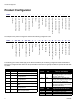
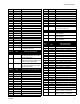
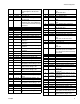
Product Configurator Product Configurator PR7F - - - - - - - - - - - - - I-J K L M N O P Q R S T U V Mixer Applicator Mounting Power Cord Flow Monitoring High Volume Side Tank High Volume Side Tank Cover Low Volume Side Tank Low Volume Side Tank Cover Tank Level Sensors Heat Zone Controller Off-Board Tank Stand G-H Dispense Valve F High Volume Side Hose High Volume Side Piston Air Motor D-E Low Volume Side Hose B-C Controls A Low Volume Side Piston Code: -
Product Configurator 4 5 6 7 8 9 A B C F G H J L M R S T U W X Y Z 140, Available in Nylon Only 160 180 200 220 240 260 280 300 320 360 400 440 480 520 560 600 640 720 800 880 960 Custom High Volume side, consult factory (stainless steel only) Code D Part A LC1___ B LC2___ C LC3___ Code E Part 1 2 3 4 5 6 7 8 9 A B C F G H 312759R Low Volume Side Piston and Metering Tube Material Nylon Piston, Stainless Steel Metering Tube (last three digits of part number is the mm2 piston size) UHMWPE Piston
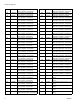
Product Configurator 6 C3 LC0163 C4 LC0164 C5 LC0165 C6 LC0166 C7 LC0167 C8 LC0168 C9 LC0169 CA LC0170 CB LC0171 CC LC0172 CD LC0173 CE LC0174 D1 LC0175 D2 LC0176 D3 LC0177 D4 LC0178 D5 LC0179 D6 LC0180 D7 LC0181 D8 LC0182 D9 LC0183 DA LC0184 DB LC0185 DC LC0186 DD LC0187 DE LC0188 E1 LC0190 Recirculating, On-Board Tanks, 3/16 in. (4.8 mm) - 15 ft (4.6 m) Recirculating, On-Board Tanks, 1/4 in. (6.5 mm) - 2.5 ft (0.
Product Configurator GH LC0406 GJ LC0407 GK LC0432 GL LC0433 GM LC0434 GQ LC0435 GR LC0436 GS LC0437 GT LC0438 GU LC0439 GW LC0440 GX LC0441 GY LC0442 G1 LC0443 G2 LC0444 G3 LC0445 G4 LC0446 G5 LC0447 HA LC0472 HB LC0473 312759R High Pressure, 3/4 in. (19 mm) - 10 ft (3.0 m) High Pressure, 3/4 in. (19 mm) - 15 ft (4.6 m) High Pressure, Recirculating, On-Board Tanks, 3/8 in. (9.5 mm) - 2.5 ft (0.6 m) High Pressure, Recirculating, On-Board Tanks, 3/8 in. (9.
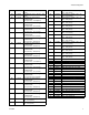
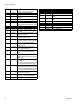
Product Configurator Code M Part Applicator Mounting Code P Part High Volume Side Tank N LC0294 1 LC0292 N 1 2 3 N/A 256896 255241 255250 2 3 LC0293 256439 4 255251 5 255281 6 255282 7 255283 8 LC0235★ 9 LC0236★ A B C LC0013★ LC0012★ 255285★ D LC0156 E LC0157 F 255284★ G H LC0254★ LC0255★ J K LC0054 LC0158 L M P LC0259 LC0055 LC0159 R S LC0260 LC0126 T LC0127 U LC0128 V LC0238★ None No Tanks, 1 1/2 in.
Product Configurator W LC0129 X Y Z LC0160 LC0297 LC0237★ --- ★ 8 L, Twin Polyethylene Tanks and Lids, Two 240V Agitators, with Shut-Off Valves Accumulator, Fluoroelastomer Accumulator, EP 7.5 L, Stainless Steel, High Level Sensors, 240V Heat When ordering tanks for spare or replacement parts, refer to Parts section of the PR70 and PR70v Feed Systems manual.
Product Configurator R LC0052 Off-Board Vacuum De-gas, Electric Agitator, Fill Port, Slinger - 60 L On-Board, Pneumatic Agitate On-Board, Pneumatic Agitate, De-gas On-Board, Pneumatic Agitate, De-gas, Fill Port Off-Board Pneumatic Agitator - 30 L Off-Board Pneumatic Agitator - 60 L Off-Board Vacuum De-gas, Pneumatic Agitator, Fill Port, Slinger - 30 L S T U LC0130 LC0131 LC0132 V W Z LC0142 LC0143 LC0146 Code T Part Tank Level Sensors N 2 N/A LC0278 3 LC0279 4 LC0282 5 LC0281 6 LC0280 7
Warnings Warnings The following warnings are for the setup, use, grounding, maintenance, and repair of this equipment. The exclamation point symbol alerts you to a general warning and the hazard symbol refers to procedure-specific risk. Refer back to these warnings. Additional, product-specific warnings may be found throughout the body of this manual where applicable. WARNING ELECTRIC SHOCK HAZARD Improper grounding, setup, or usage of the system can cause electric shock.
Warnings WARNING FIRE AND EXPLOSION HAZARD Flammable fumes, such as solvent and paint fumes, in work area can ignite or explode. To help prevent fire and explosion: • Use equipment only in well ventilated area. • Eliminate all ignition sources; such as pilot lights, cigarettes, portable electric lamps, and plastic drop cloths (potential static arc). • Keep work area free of debris, including solvent, rags and gasoline.
Component Identification Component Identification 101 103 104 110 102 ti13389b 119 Key: 111 101 102 103 104 105 106 105 107 108 109 110 111 112 119 Tanks Dispense Head Snuff Back Adjustment Knob Advanced Display Module System Air Pressure Regulator System Air Pressure Relief Switch Power Switch Water Separator Air Inlet Shield Locking Screws Machine Shield Agitator Flow Meters 106 ti13388b 109 110 107 108 FIG.
Component Identification 113 116 101 117 103 118 111 104 115 110 112 102 ti12387b 113 114 Key: 101 102 103 104 105 106 107 108 109 110 111 112 113 114 115 116 117 118 105 106 Tanks Dispense Head Snuff Back Adjustment Knob Advanced Display Module System Air Pressure Regulator System Air Pressure Relief Switch Power Switch Water Separator Air Inlet Shield Locking Screws Machine Shield Agitator De-gas Valve Tree Tank Air Pressure Gauge Tank Stand Refill Port Accumulator Accumulator Air Pressure Reg
Component Identification Advanced Display Module (ADM) If an invalid key is pressed, the Advanced Display Module will sound three quick beeps to notify the user. AJ AB AC AC AD AG 1 2 3 4 5 6 7 8 9 0 . AF AG AH AE Key: AB AC AD AE Machine Disable Mode Key Soft Keys Directional Keypad Numeric Keypad AF AG AH AJ Abort/Cancel Key Enter Key Alternate Setup/Operation Screens Module Status LED FIG.
Screen Navigation Diagram Screen Navigation Diagram The black arrows in the diagram denote which arrow on the directional keypad to press to move to the respective screen. If the password is enabled, the password will need to be entered to access the Setup screens. Use the numeric keypad to enter the password then press the Enter button ( ). Operation Screens Home Data #1 Errors #1 Events #1 Data #2 Errors #2 Events #2 Data #... Errors #... Events #...
Grounding Grounding access to compressed air and AC power and is well ventilated. 2. Place the machine on the designated location. Allow the machine to rest on the rubber feet provided. Mount Machine, if Needed This product must be grounded. In the event of an electrical short circuit, grounding reduces the risk of electric shock by providing an escape wire for the electric current. This product is equipped with a cord having a grounding wire with an appropriate grounding plug.
Installation Electrical Requirements Improper wiring may cause electric shock or other serious injury if work is not performed properly. Have a qualified electrician perform any electrical work. Be sure your installation complies with all National, State and Local safety and fire codes. 6. Using the power cord provided, connect AC power (100-240V, 50/60 Hz, single-phase) to the machine. Ground System The equipment must be grounded.
Installation Tank Refill Kit 256577 Installation The tank refill kit is shipped uninstalled. The tank refill kit can be installed on the lid of the tank or on the side of the tank. See FIG. 5 and FIG. 7. Install the tank refill kit in the tank lid if using heat or agitation or if a slinger blade is installed in the tank. Install the tank refill kit in the side of the tank if using thicker materials. Pouring thick materials into the tank from the lid can result in air added to the material.
Installation Tank Refill Kit Side Installation 1. Use PTFE tape and the fittings supplied to install the refill kit as shown in FIG. 7. 2. For tank refill kits installed on the A side tank, plug the tank refill kit power cord into the “A” connector located at the back of the machine. See FIG. 8. For tank refill kits installed on the B side tank, plug the tank refill kit power cord into the “B” connector located at the back of the machine. See FIG. 8. 30 L or 60 L Tanks ti13385a ti12583a FIG.
Startup Startup 1. Locate power switch (107) at rear of machine and turn power on. The display module will automatically turn on and begin to load. 2. Slide the system air pressure relief switch (106) up. It is the yellow tab at the left, rear of the machine. The hole in the tab should not be showing. 3. If the machine is in Disabled Mode, press the Select Operating Mode button ( ) repeatedly to exit Disabled mode and to select a new operating mode. Press the Enter button ( operating mode.
Setup Setup Setup Screens Edit Screens GB GH GH GG GA GK GJ GK Edit Screen #2 Shown GC GD GE GF Key: GA Enter/Exit Screen button GB Active Screen Name GC Shot Number (Edit Screen #1) or Sequence Position (Edit Screens #2-#5) GD Shot Number (Edit Screens #2-#5 only) GE Shot Size GF Delay Between Shots (Edit Screens #2-#5 only) GG Enable/Disable Auto Sequencing Mode (Edit Screens #2-#5 only) GH Adjacent Screen Names GJ Active Screen Number GK Adjacent Screen Numbers FIG.
Setup Overview Edit Shot Sequence There are five Edit screens. Edit Screen #1 is the Shot Editing screen and Edit Screens #2-#5 are Sequence Editing screens. Edit Screen #1 shows Shot #1 through Shot #50. Each shot has a defined shot size that is measured in grams. To change which Shot Numbers (GD) from Edit Screen #1 are used in a sequence, use the following procedure. Edit Screens #2-#5 show Sequence A through Sequence G. Each sequence has ten positions; shown as A0 to A9 in FIG. 10.
Setup 7. Press the Enter/Exit Screen button (GA) to exit the screen. Edit Auto-Sequencing To edit whether the machine automatically performs all shots in a sequence, use the following procedure. 1. Navigate to the Edit Screen that contains the Sequence to be changed. See Screen Navigation Diagram, page 16. b. Use the numeric keypad to enter the desired delay time in seconds. c. Press the Enter button ( ) to accept the delay and exit editing mode. 7.
Setup Calibration Screen FJ FK FK FB FA FC FF FD FG FH FE Key: FA FB FC FD FE Start/Stop Shot Update Piston Extended Position Update Piston Retracted Position Update Piston Engaged Position Piston Phasing FF FG FH FJ FK Adjust Open Dispense Valve Timing Initiate Small Calibration Shot Initiate Large Calibration Shot Active Screen Name Adjacent Screen Names FIG.
Setup Options Screens Fluid Options, Screen #1 HS HB HA HC HD HE HK HL HM HR HS HF HG HU HH HJ HT HV HU HN Key: HA HB HC HD HE HF HG HH HJ Enter/Exit Screen Purge Timer Enable/Disable Purge Timer Delay Purge Timer Shot Size Purge Timer Alarm (seconds) Recirculation Timer Enable/Disable Recirculation Timer Delay Recirculation Timer Shot Size Recirculation Timer Alarm (seconds) HK Low Level Sensors Enable/Disable (For FCMB Systems) HL Tank A High Level Sensor Options HM Tank B High Level Sensor Option
Setup 2. Use the arrow keys to navigate to the item to be changed. Level Sensors See the Feed Systems manual referenced at the beginning of this manual for Vacuum Auto-Fill procedure. The Low Level Sensors can be enabled or disabled. Disabling the low level sensors disables low level alarms. If the Low Level Sensors are disabled, the tank icons on the Home screen will be grayed out. 3. Use the numeric keypad to enter the new value. 4. Press the Enter button ( value. ) to accept the new 5.
Setup Heat Options, Screen #2 JP JN JP JB JC JD JA JS JE JF JG JR JH JJ JK JS JL JM Key: JA JB JC JD JE JF JG JH Enter/Exit Screen Enable/Disable Tank Heater Zone Zone Number Used for Tank Heat Control Tank Heat High Temperature Alarm Tank Heat Temperature Setpoint Tank Heat Low Temperature Alarm Tank Heat Blanket Temperature Setpoint Enable/Disable Hose Heater Zone JJ JK JL JM JN JP JR JS Zone Number Used for Hose Heater Control Hose Heater High Temperature Alarm Hose Heater Temperature Setpoi
Setup Enable/Disable Heat Options Edit Temperature Settings All heat options can be enabled or disabled. All options that are installed should be enabled and all that are not installed should be disabled. All enabled heat options can be turned on and off from the Home Screen, see page 53. To enable or disable heat options, perform the following procedure. 1. Press the Enter/Exit Screen button (JA) to enter the screen. 1. Press the Enter/Exit Screen button (JA). 2.
Setup System Options, Screen #3 LK LJ LK LA LM LB LC LD LE LL LM LF LG LH LN Key: LA LB LC LD LE Enter/Exit Screen Disable Dispensing Option Disable Modifying Shot Sizes Option Disable Erasing Counters Option Disable Changing Temperature Setpoint Option LF Enable Piston Auto-Retract Option LG Low Temperature Disables Dispense Option LH LJ LK LL LM LN Silent Mode Option Active Screen Name Adjacent Screen Names Active Screen Number Adjacent Screen Numbers Disables Pump Stationary During Dispense Time
Setup Dispense Check Options, Screen #4 PJ PH PJ PA PL PB PC PD PK PL PE PF PG Key: PA PB PC PD PE PF Enter/Exit Screen Change in Velocity Change in Pressure Change in Ratio or Volume Ratio Type (Volume or Weight) A Side Flow Meter Calibration Factor PG PH PJ PK PL B Side Flow Meter Calibration Factor Active Screen Name Adjacent Screen Names Active Screen Number Adjacent Screen Numbers FIG.
Setup Ratio Type Fluid ratio can be monitored as either weight-ratio or volume-ratio. If the ratio type selected is “Volume”, the calibration factor for each installed flow meter must be entered in the calibration factor fields (PF, PG). The calibration factor is found on the flow meter data sheet shipped with the machine. After each shot, the ratio for that shot will be shown on the Home screen. If weight-ratio is selected, the ratio will be shown to the left of the piston position graphic.
Setup Flow Meter Calibration, Screen #5 RF RK RJ RK RG RA RM RB RC RD RE RL RM RH Key: RA RB RC RD RE RF Enter/Exit Screen Average Calibration Weight Material Weight Entry Cycles per Gram Total Cycles A Side Information RG RH RJ RK RL RM B Side Information A to B Weight Ratio Active Screen Name Adjacent Screen Names Active Screen Number Adjacent Screen Numbers FIG. 19 Proper calibration of the flow meters ensures that ratio and weight monitoring perform optimally.
Setup Advanced Setup Screen KM KN KN KA KB KL KC KD KE KF KG KH KJ KK Key: KA KB KC KD KE KF KG Language Selection Temperature Units Selection Date Format Month Day Four Digit Year Hours (24 Hour Clock) KH Minutes KJ Numeric Password (four digits allowed) KK Screen Saver KL Enter/Exit Screen KM Active Screen Name KN Adjacent Screen Names FIG. 20 Password Date Formats If a password other than “0” is entered, the password is automatically enabled. The password protects entry into the setup screens.
Setup System Data Screen MM MA Key: MA MB MC MD Enter/Exit Screen Current Machine Cycles Counter Total Machine Cycles Counter Advanced Display Module Software Version ME Fluid Control Module #1 Software Version MF Fluid Control Module #2 Software Version MG Temperature Control Module Zone #1 Software Version ML MM MB MC MN MP MD ME MF MG MH MJ MK MH Temperature Control Module Zone #2 Software Version MJ Temperature Control Module Zone #3 Software Version MK Temperature Control Module Zone #4 Software
Setup Manual Screen EJ EH EJ EG EA EF EB 1 EC 1 ED EE 1 Valve will open for approximately two seconds. Key: EA EB EC ED EE EF EG EH EJ Extend Piston Command Retract Piston Command Tank A Refill Valve Command Open Tank B Refill Valve Command Open Dispense Valve Command Close Dispense Valve Command Open Revert to Automatic Dispense Valve Operation Active Screen Name Adjacent Screen Names FIG. 22 The Manual screen overrides control of some machine actions.
Setup Edit Settings Prepare Machine for Calibration • Edit Display Settings: See Advanced Setup Screen, page 34. 1. Ensure that both piston shafts are screwed all the way into the drive block. • Edit Shots and Sequences: See Edit Screens, page 22. • Edit Recirculation and Purge Timers: See Fluid Options, Screen #1, page 26. • Edit Level Sensor Settings: See Fluid Options, Screen #1, page 26. • Edit Temperature Control Settings: See Heat Options, Screen #2, page 28.
Setup Manually Move the Piston Drive Block Retracted Piston Position 9. With air pressure applied to the machine, press the Retract Piston button ( ). In the steps below, ensure pressure is off or piston may activate and pinch fingers against machine block. 10. Press the Start/Stop Shot button ( ). The piston will fully retract and a number from 1250 to 1600 will be displayed next to the Retract Piston button.
Setup Prime the Dispense Head 8. Select a large size shot. CAUTION If the dispense head is not primed, chemical crossover may occur resulting in cured material in the dispense head, hoses, and/or pumps. 9. Hold a waste container at the end of the dispense head (102) and press the Start/Stop Shot button See FIG. 24. ( 1. Remove static mixer from the dispense head (102) if installed. 2. Turn snuff-back adjustment knob (103) fully clockwise.
Setup Phasing Adjustment Adjust Dispense Quantity 6. Press the Enter/Exit Phasing button ( phasing mode. 7. Press the Start/Stop Shot button ( ) to enter ) or the foot- switch to dispense a very small amount of material. 8. Adjust the displayed percentage if more than a couple drops of either material was dispensed or if no material was dispensed from both sides. FIG.
Setup • Adjust Phasing If the B side material exits the dispense nozzle before the A side material ( 303 ): a. Use two 13 mm wrenches to break loose the locking nut (302) from the phase adjustment screw (303) on the A material side. 302 301 b. Hold the phase adjustment screw (303) stationary with a 13 mm wrench. c. Use a 7 mm wrench to turn the piston shaft (301) counterclockwise 1/4 turn or less to move the A piston forward.
Setup Adjust Dispense Valve Snuff Back At the end of a shot, a small amount of material is drawn back into the static mixer to prevent extra material from being dispensed. If too much snuff back occurs air will enter the static mixer and can travel up into the dispense valve. If too little snuff back occurs the materials may drip out of the static mixer and affect dispense quantity.
Setup Adjust Open Dispense Valve (ODV) Timing 1. Navigate to the Calibration screen. See Screen Navigation Diagram, page 16. FF 2. Press the Adjust Open Dispense Valve Timing button (FF). 3. Use the numeric keypad to enter a value for the ODV Timing. Use the +/- key to switch from positive to negative and negative to positive. 4. Press the Enter button ( Key: FF Adjust Open Dispense Valve Timing FIG. 27 ) to accept the new value or press the Abort/Cancel button ( ) to keep the previous value.
Setup Calibrate Dispense Weight Ratio (PR70v only) Maximum Minimum A Tube B Tube Ratio by Ratio by Piston Size Piston Size Volume Volume (1:1 Position) (2:1 Position) (mm2) (mm2) 203 202 The PR70v base unit can dispense volume ratios in the range of 1:1 to 24:1. The range of A to B cylinder size ratios is 1:1 to 12:1. The mechanical ratio arm multiplies the constant cylinder size ratio by a range of 1:1 to 2:1 depending on the ratio arm adjustment.
Setup l. 5. Change the mechanical ratio adjustment to the desired setting (1.19 in the example) as follows. a. Ensure the machine pistons are in the retracted position. b. Ensure the purge timer is off and the machine is not in recirculation mode. c. Use system air pressure regulator (105) to decrease air pressure in the system to zero. Loosen the hex head cap screws (204) on the ratio adjustment pivot. m.
Setup 6. Navigate to the Home screen. See Screen Navigation Diagram, page 16. 7. Phase the machine. See Phasing Adjustment, page 40. Perform Weight Ratio Check Shot 8. Install ratio check nozzle onto dispense valve. 21. Divide the weight of container “A” by the weight of container “B” to get the weight ratio of the dispensed materials. 22. Repeat steps 16 through 21 at least two more times for an overall total of at least three ratio check shots, or repeat as needed. 23.
Setup Shot Calibration 18. Enter weight in grams using numeric keypad. To dispense accurate quantities of material, a few small and large calibration shots must be performed. Once the weights are entered, the machine will calculate an average weight for the small and large calibration shots. 19. Press the Enter button ( ) to accept the number or press the “0” button on the numeric keypad repeatedly to clear out the entry then re-enter. Prepare for Calibration 1.
Setup Flow Meter Calibration Prepare for Calibration 1. Verify the piston position is calibrated. See Piston Position Calibration, page 37. 2. Verify the dispense head is properly primed. See Prime the Dispense Head, page 39. 15. Place container “A” under the A material output of the ratio check nozzle. Place container “B” under the B material output of the ratio check nozzle. 16. Press the Flow Meter Calibration button ( enter calibration mode. 17. Press the Start/Stop Shot button ( 3.
Setup External Control Interface Setup Connector #2 NOTE: Connector #2 is for use with systems with an Advanced Display Module only. Customer Supplied Dry Contact/Relay NOTE: View shown is looking at pins on end of cable. 2 3 1 5 4 Brown Gray Black SHOT SEL - BIT 0 SHOT SEL - BIT 3 SHOT SEL - BIT 2 Blue White COMMON SHOT SEL - BIT 1 Connector #1 Customer Supplied Dry Contact/Relay NOTE: Connector #1 is for use with all systems. NOTE: View shown is looking at pins on end of cable.
Setup Fault-Output Status Line The Fault-Output status line (“FAULT-OUTPUT” in FIG. 32, Connector #1, Pin #5) indicates whether there is an active error. Active errors typically stop system operation. After using the display module to acknowledge the error, normal operation will be allowed. The output of the Fault-Output status line is a “high” +24 VDC signal when an active error exists. The output is a “low” +15 VDC signal when there is not an active error. See FIG.
Setup Shot Number Selection Lines The external control interface has four lines used to select a shot number (“SHOT - SEL - BIT” lines in FIG. 32, Connector #2, Pins #1, 2, 4, 5). The default for each line is a “high” +24 VDC output. To select a shot, the external control will need to ground a certain combination of lines to the Return line (Connector #2, Pin #3) for at least 0.100 seconds to create a “low” signal for each line. Each combination refers to one shot number from Shot #1 to Shot #15.
Setup External Control Interface Timing The following timing diagram illustrates changing the shot number to Shot #13 then dispensing that shot. Interrupt - Cancel Fault-Out Status Ready-Out Status SHOT-SEL-BITO SHOT-SEL-BIT1 SHOT-SEL-BIT2 SHOT-SEL-BIT3 Shot Request 100 mS 170 mS 170 mS 0 40 80 120 160 200 240 280 320 360 400 440 TIME (milliseconds) FIG.
Operation Operation Operation Screens Home screen Read all manufacturer’s warning and material MSDS to know the specific hazards of the materials used. BJ BY BZ B1 BZ BK BL BM BA BG BB BN BP BC BX 2 BE BD BF 1 BR BS BU BW BV BT 1 BT1 1 Temperature status will only be displayed if heaters are installed and enabled. 2 Only visible if Auto-Refill is installed and the High Level Sensors option on the Fluid Options Screen is set to an option other than Disabled.
Operation Change Operating Mode Shot Mode Operation The available operating modes are Shot, Sequence, Operator (Manual), Recirculation, and Disabled mode. The active operating mode name will be shown on the Home screen under the date and time. See FIG. 35 on page 53. 1. From the Home screen, press the Select Operating Mode button ( ). 2. Press the Up Arrow button ( button ( ) or the Down Arrow ), or repeatedly press the Select Operat- ing Mode button ( ) to scan through the operat- ing modes. 3.
Operation Perform a Shot 4. Press the Enter button ( 1. Select Shot Mode. See Change Operating Mode, page 54. ) to accept the new sequence or press the Abort/Cancel button ( ) to keep the previous sequence. 2. Press the Start/Stop Shot button ( ) to start a Change Active Position in Sequence shot. 1. Select Sequence Mode. See Change Operating Mode, page 54. The Start/Stop Shot button ( Abort/Cancel button ( ) changes to the 2. Press the Active Shot/Sequence button (BA). ) during the shot.
Operation 3. Press the Start/Stop Shot button ( Operator (Manual) Mode Operation ) to start a shot. The Start/Stop Shot button ( Abort/Cancel button ( ) changes to the ) during the shot. Press the Abort/Cancel button on the screen ( Abort/Cancel button on the keypad ( ) or the ) to can- cel the shot if necessary. When the shot is complete or if the shot is aborted, the Abort/Cancel button on the screen ( changes back to the Start/Stop Shot button ( ).
Operation Recirculation Mode Operation 2. Ensure system air pressure is at the standard operating setting. 3. Navigate to the Fluid Options Setup Screen. See Screen Navigation Diagram on page 16. 4. Configure the shot size, timer duration, and alarm point, then enable the Recirculation Timer. See Fluid Options, Screen #1 on page 26. 5. Navigate to the Home screen. See Screen Navigation Diagram on page 16. 6. Press the Start/Stop Shot button ( ti12392a FIG.
Operation Disabled Mode Operation The machine will not dispense in this mode. All outputs to the solenoid valves are disabled and the Start/Stop Shot button ( ) is inactive. Heat controls remain active. Pressing the Machine Disable Mode key ( ) will enter Disabled Mode and disable heat. Select Disabled mode using the Select Operating Mode button ( ) to enter Disabled Mode without disabling heat.
Operation Data Screens CC CA CB Key: CA Shot Number Column CB Shot Counter Column CC Enter/Exit Screen FIG. 37 The data screens show the shot counters for all shots and shot sequences. Data screen #1 shows the shot counters for all shots. Data screens #2-#5 show the shot counters for sequences A through G, with two sequences shown per screen. Reset Shot and Sequence Counters 1. Navigate to the correct Data Screen. See Screen Navigation Diagram on page 16. 2. Press the Enter/Exit Screen button (CC). 3.
Operation Error Screens DA DB DC 1 DD 1 See Troubleshooting section, page 69. Key: DA DB DC DD Error Number Date Error Occurred Time Error Occurred Error Details FIG. 38 The Errors Screen tracks all of the errors that have occurred on the machine. The latest error will appear at the top of the list with date, time, and code-class-event information. For more information on the code-class-event information, see Troubleshooting section, page 69.
Operation Events Screen NA NB NC ND Key: NA NB NC ND Event Number Date Event Occurred Time Event Occurred Event Details FIG. 39 The Events Screen shows a history of events for the machine with details of the event including date and time. The following is a list of events tracked on the Events Screen.
Operation Auto-Refill 4. Press the Initiate Auto-Refill button ( See Fluid Options, Screen #1 on page 26 for a description of each Auto-Refill mode. Enter button ( ) or the ) to confirm. 5. If necessary, press the Abort/Cancel button ( With Level Sensors installed, Auto-Refill can be used. There are multiple Auto-Refill modes ranging in function. For details on the different modes, see Fluid Options, Screen #1 on page 26. The tank icons on the Home Screen display the status of each tank.
Operation Temperature Control Purge Timer Purge Timer settings can be changed from the Fluid Options Setup Screen, see page 26. BC BE BD BF BR BS BT BT1 The Tank Fluid Temperature Setpoint (BR), Tank Fluid Temperature (BS), Hose Heater Temperature (BT1), and Hose Heater Temperature Setpoint (BT) display the status of the each of the options. To turn the Tank Blanket Heaters or Hose Heaters on or off, press the Tank or Hose Heater On/Off button (BC, BD, BE, BF).
USB Data USB Data USB Logs Download Procedure During operation, PR70 stores system and performance related information to memory in the form of log files. PR70 maintains two log files: error logs and event logs. Follow the Download Procedure on this page to retrieve log files. 1. Insert USB flash drive into USB port. Error Log The error log file name is 1-ERROR.CSV and is stored in the DOWNLOAD folder. The error log maintains a record of the last 1,000 errors.
Pressure Relief Procedure Pressure Relief Procedure Shutdown If the machine is to remain idle for an extended period of time, perform the following steps. 1. Place a waste container below the dispense valve. 1. Place a waste container below the dispense valve. 2. Navigate to the Manual screen. See Screen Navigation Diagram on page 16. 3. Press the Open Dispense Valve button on the Manual screen to relieve chemical pressure. 4. Press the Machine Disable Mode button ( ). 2.
Maintenance Maintenance Schedule Action Schedule Procedure Check Water/Air Separator Daily before use 1. Check water/air separator for water. 2. Open valve at base of water/air separator to purge water. Check Desiccant Dryer (only installed if chemical is moisture sensitive) Daily before use 1. Check the color of the desiccant 2. Replace as required. Check Tanks Daily before use 1. Check material levels and refill as necessary. 2. Verify the material reservoirs are vented properly.
Maintenance 5. Lubricate all parts with a thin coat of mesamoll or silicon oil. 6. Reassemble dispense head. See manual 312185 for details. Lubricate Gear Box of Pneumatic Air Motor 01/0368-1/11 7. Reinstall dispense head on machine. NOTE: This section does not apply to pneumatic air motors 24J182 or 24J183. Flush Pneumatic Air Motor 82/0216/11 Check Oil Level Perform the following procedure every two days. 1. Remove oil fill plug and check oil level.
Maintenance Install Upgrade Token This procedure applies to the Advanced Display Module (ADM) and Fluid Control Module (FCM). 1. Disconnect power to the module. 2. Remove token access panel. See FIG. 41. Fluid Control Module, Advanced Display Module Low Power Temperature Control Module ti12904a1 ti12334a FIG. 41: Remove Access Panel 3. Insert and press firmly token into slot. NOTE: There is no preferred orientation of the token. 4. Restore power to the module.
Troubleshooting Troubleshooting Before starting any troubleshooting procedures, perform the following procedure. See PR70 and PR70v Repair Parts manual referenced at the beginning of this manual for detailed procedures. 2. Disconnect AC power from the machine. 1. Relieve pressure. See Pressure Relief Procedure, page 65. Try the recommended solutions in the order given for each problem to avoid unnecessary repairs.
Troubleshooting Problem Cause Solution Material dispensed not correct weight Specific gravity of one or more of the Recalibrate machine. two materials has changed since calibration Machine dispensing off ratio Pumps drawing material back from valve hose 70 Machine air pressure has changed since calibration. Readjust air pressure regulator to value used when machine was calibrated, or recalibrate machine. Not enough material in one or more tanks Check tank levels; fill and prime as necessary.
Troubleshooting Error Codes Code-Class-Event Shown on Errors Screen Description 050X-A-Improper System Cal Improper Calibration 5 06CX-A-Invalid Key Token No or Invalid Key Token 4 A401-A-Over Current Z1 Heater Over Current, Zone #1 7 A402-A-Over Current Z2 Heater Over Current, Zone #2 7 A403-A-Over Current Z3 Heater Over Current, Zone #3 7 A404-A-Over Current Z4 Heater Over Current, Zone #4 7 A4C1-A-Fan Over Current Z1 High Relay 2 Current, Zone #1 7 A4C2-A-Fan Over Current Z2 High
Troubleshooting Code-Class-Event Shown on Errors Screen Description System Behavior Ref F2B-Low Flow B Side Low B Side Fluid Flow, relative to calibration and user-input allowable variance. See Dispense Check Options, Screen #4 on page 31.
Troubleshooting Code-Class-Event Shown on Errors Screen Description System Behavior Ref P7DX-D-Out of Phase Machine Out of Phase, relative to calibration and user-input allowable variance. See Dispense Check Options, Screen #4 on page 31. 6 R2-A:B Ratio Low A:B Ratio is low, relative to calibration and user-input allowable variance. See Dispense Check Options, Screen #4 on page 31. 6 R3-A:B Ratio High A:B Ratio is high, relative to calibration and user-input allowable variance.
Troubleshooting Code-Class-Event Shown on Errors Screen Description System Behavior Ref T804-D-No Heat Z4 No Temperature Rise, Zone #4 8 T901-A-Temp Switch Cutoff Z1 Over Temp Switch Open, Zone #1 7 T902-A-Temp Switch Cutoff Z2 Over Temp Switch Open, Zone #2 7 T903-A-Temp Switch Cutoff Z3 Over Temp Switch Open, Zone #3 7 T904-A-Temp Switch Cutoff Z4 Over Temp Switch Open, Zone #4 7 T9C1-A-Control Shutdown Z1 PCB Over Temperature, Zone #1 7 T9C2-A-Control Shutdown Z2 PCB Over Temperatu
Troubleshooting System Behavior Reference System Behavior Description 4 When this error is generated, a pop-up with the error-code will be shown continuously until the error condition is corrected. The machine and display module are completely disabled until the error condition is corrected. 5 When this error is generated, a pop-up with the error-code will be shown.
Kits Kits Mixer and Shroud Options Part LC0063 LC0057 LC0058 LC0059 LC0060 LC0061 LC0062 LC0077 LC0078 LC0079 LC0080 LC0081 LC0083 LC0082 LC0084 LC0085 LC0086 LC0087 LC0088 LC0089 LC0090 Description Mixer, 3/16 in. (6.5 mm) x 32, 10 Mixers with shroud Mixer, 1/4 in. (6.5 mm) x 24, 10 Mixers with shroud Mixer, 3/8 in. (9.8 mm) x 24, 10 Mixers with shroud Mixer, 3/8 in. (9.8 mm) x 36, 10 Mixers with shroud Mixer, 3/8 in. (9.8 mm) Combo, 10 Mixers with shroud Mixer, 3/16 in. (4.
Kits Vacuum Kits Refill Kits These vacuum kits contain the parts necessary to attach a vacuum pump to the tanks. On-Board Vacuum Kits Refill Kits 256659 and 256660 are designed to turn on and off a transfer pump as needed to keep the tanks at the proper fluid level. Tank Refill Kit 256577 is designed to open and close a valve to allow fluid to flow into the tank from an always-on transfer pump. Tank Refill Kit 256577 includes the parts necessary to install on the base or lid of a 7.
Dimensions Machine with On-Board Tanks A D ti12621b ti12622b C B PR70 † Assembly Dimensions, in. (mm) Stainless Steel Tanks Polyethylene Tanks Ref A B C D No Agitators With Agitators 3L 7.5 L, No Agitators 7.5 L, with Agitators 26.4 (670) 18.5 (470) 30.6 (778) 13.4 (340) 38.6 (980) 18.5 (470) 30.6 (778) 13.4 (340) 28.2 (716) 15.5 (394) 30.6 (778) 13.4 (340) 38.2 (970) 15.5 (394) 30.6 (778) 13.4 (340) 39.9 (1013) 15.5 (394) 30.6 (778) 13.4 (340) PR70v † Assembly Dimensions, in.
Dimensions Machine with Off-Board Tanks A D ti12624c ti12623c C B PR70 † Assembly Dimensions, in. (mm) 30 L Tank Ref A B C D 60 L Tank No Agitators With Agitators No Agitators With Agitators 75.7 (1923) 32.1 (815) 29.3 (744) 16.0 (406) 83.4 (2118) 32.1 (815) 29.3 (744) 16.0 (406) 64.9 (1648) 32.1 (815) 29.3 (744) 16.0 (406) 89.5 (2273) 32.1 (815) 29.3 (744) 16.0 (406) PR70v † Assembly Dimensions, in.
Technical Data Metering Pump Effective Area . . . . . . . . . . . . . . . . . . . . . 80 to 960 mm2 (0.124 to 1.49 in.2) per side Small Air Cylinder Effective Area . . . . . . . . . . . . . . . . . . 4560 mm2 (7.07 in.2) Large Air Cylinder Effective Area . . . . . . . . . . . . . . . . . . 10260 mm2 (15.9 in.2) Maximum Stroke Length . . . . . . . . . . . . . . . . . . . . . . . . . 38.1 mm (1.50 in.) Minimum Stroke Length . . . . . . . . . . . . . . . . . . . . . . . . . 5.8 mm (0.23 in.) Volume per Cycle .
Technical Data 312759R 81
Graco Standard Warranty Graco warrants all equipment referenced in this document which is manufactured by Graco and bearing its name to be free from defects in material and workmanship on the date of sale to the original purchaser for use. With the exception of any special, extended, or limited warranty published by Graco, Graco will, for a period of twelve months from the date of sale, repair or replace any part of the equipment determined by Graco to be defective.