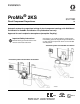
Installation ® ProMix 2KS 312778D EN Plural Component Proportioner Automatic system for proportional mixing of plural component coatings, with Wall Mount Fluid Station or RoboMix Fluid Station. For professional use only. Approved for use in explosive atmospheres (except the EasyKey). Important Safety Instructions Read all warnings and instructions in this manual. Save these instructions. See pages 4-7 for model information, including maximum working pressure. Equipment approval labels are on page 3.
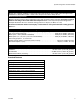
Contents Related Manuals . . . . . . . . . . . . . . . . . . . . . . . . . . . 3 15V256 Automatic Upgrade Kit . . . . . . . . . . . . . . . 3 Equipment Approvals . . . . . . . . . . . . . . . . . . . . . . . 3 System Configuration and Part Numbers . . . . . . . 4 Wall Mount Fluid Station Configurator Key . . . . . 4 RoboMix Fluid Station Configurator Key . . . . . . . 6 Accessories . . . . . . . . . . . . . . . . . . . . . . . . . . . . . . . 9 Warnings . . . . . . . . . . . . . . . . . . . . . . . . . . .
Related Manuals Related Manuals Equipment Approvals Component Manuals in English Equipment approvals appear on the following labels which are attached to the Fluid Station and EasyKey™. See FIG. 1 on page 4 and FIG. 2 on page 6 for label locations.
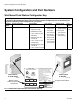
System Configuration and Part Numbers System Configuration and Part Numbers Wall Mount Fluid Station Configurator Key The configured part number for your equipment is printed on the equipment identification labels. See FIG. 1 for location of the identification labels. The part number includes one digit from each of the following six categories, depending on the configuration of your system.
System Configuration and Part Numbers Hazardous Location Approval Models using a G3000, G3000HR, or intrinsically safe Coriolis meter for both A and B meters are approved for installation in a Hazardous Location - Class I, Div I, Group D, T3 or Zone I Group IIA T3. Maximum Working Pressure Maximum working pressure rating is dependent on the fluid component options selected. The pressure rating is based on the rating of the lowest rated fluid component. Refer to the component pressure ratings below.
System Configuration and Part Numbers RoboMix Fluid Station Configurator Key The configured part number for your equipment is printed on the equipment identification labels. See FIG. 2 for location of the identification labels. The part number includes one digit from each of the following six categories, depending on the configuration of your system.
System Configuration and Part Numbers Hazardous Location Approval Models using a G250 or G250HR for both A and B meters are approved for installation in a Hazardous Location Class I, Div I, Group D, T3 or Zone I Group IIA T3. Maximum Working Pressure Maximum working pressure rating for RoboMix Systems is 190 psi (1.31 MPa, 13.1 bar). Check the identification label on the EasyKey or RoboMix fluid station for the system maximum working pressure. See FIG. 2.
System Configuration and Part Numbers 8 312778D
Accessories Accessories Accessory 15V354 Third Purge Valve Kit 15V202 Third Purge Valve Kit 15V536 Solvent Flow Switch Kit 15V213 Power Cable, 100 ft (30.5 m) 15G710 Fiber Optic Cable, 100 ft (30.5 m) 15G614 Flow Control Extension Cable, 40 ft (12.
Warnings Warnings The following warnings are for the setup, use, grounding, maintenance, and repair of this equipment. The exclamation point symbol alerts you to a general warning and the hazard symbols refer to procedure-specific risks. When these symbols appear in the body of this manual, refer back to these Warnings. Product-specific hazard symbols and warnings not covered in this section may appear throughout the body of this manual where applicable.
Warnings WARNING SKIN INJECTION HAZARD High-pressure fluid from gun, hose leaks, or ruptured components will pierce skin. This may look like just a cut, but it is a serious injury that can result in amputation. Get immediate surgical treatment. • Tighten all fluid connections before operating the equipment. • Do not point gun at anyone or at any part of the body. • Do not put your hand over the spray tip. • Do not stop or deflect leaks with your hand, body, glove, or rag.
Important Two-Component Material Information Important Two-Component Material Information Isocyanate Conditions Spraying or dispensing materials containing isocyanates creates potentially harmful mists, vapors, and atomized particulates. Read material manufacturer’s warnings and material MSDS to know specific hazards and precautions related to isocyanates. Prevent inhalation of isocyanate mists, vapors, and atomized particulates by providing sufficient ventilation in the work area.
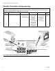
Component Identification and Definition Component Identification and Definition See Table 1, and FIG. 3 for the wall mount system components and FIG. 4 for the RoboMix system components. EK ACV Air Controls/ Filter CCM PS* BCV MS FC FO* ST MA FM * See the ProMix 2KS Repair-Parts manual for optional cable lengths. MB TI12553a FIG. 3.
Component Identification and Definition Table 1: Component Descriptions Component Description EasyKey (EK) Used to set up, display, operate, and monitor the system. The EasyKey accepts 85-250 VAC, 50/60 Hz line power and converts that power to acceptable low voltage and optical signals used by other system components.
Component Identification and Definition Table 1: Component Descriptions Component Flow Meters (MA, MB, MS) Description The following optional flow meters are available from Graco: • G3000 is a general purpose gear meter typically used in flow ranges of 75-3800 cc/min. (0.02–1.0 gal/min.), pressures up to 4000 psi (28 MPa, 276 bar), and viscosities of 20–3000 centipoise. The K-factor is approximately 0.119 cc/pulse. • G3000HR is a high resolution version of the G3000 meter.
Component Identification and Definition ACV EK CCM BCV Air Controls/ Filters PS* Purge Air RoboMix Control Air FO* FC ST * See the ProMix 2KS Repair-Parts manual for optional cable lengths. TI12552a FIG. 4.
Component Identification and Definition Air Logic In Cable Path B Supply (1/4 npt) A Supply (1/4 npt) Ground Screw Air Purge Solvent Supply (1/4 npt) TI12511a A Dump Out B Dump Out Cover is removed for clarity MB MA TI12579a FIG.
Location Location Location Requirements Intrinsically Safe Installation Requirements See FIG. 6 on page 19. Do not substitute or modify system components as this may impair intrinsic safety. For installation, maintenance or operation instructions, read instruction manuals. Do not install equipment approved only for non-hazardous location in a hazardous area. See the identification label (FIG. 1 and FIG. 2) on the EasyKey or fluid station for the intrinsic safety rating for your model.
Location FM08ATEX0074 SYSTEM ASSEMBLY CERTIFICATE NON-HAZARDOUS LOCATION ONLY ProMix 2KS EasyKey Interface Safety Barrier FM08ATEX0072 ASSOCIATED APPARATUS 250 VAC Maximum Supply Voltage HAZARDOUS (CLASSIFIED) LOCATION CLASS I, DIV I, GROUP D, T3 (US AND CANADA) CLASS I, ZONE I GROUP IIA T3 (ATEX ONLY) TAUB = -20°C TO 50°C 10’ I/S Power and Communication Cable (40’ extension option) ProMix 2KS Smart Fluid Plate (Wall Panel or RoboMix 50’ I/S Power Cable (3’, 6’, 10’, 15’, 25’, 100’ options) FM08ATEX
General Information General Information • • • Reference numbers and letters in parentheses in the text refer to numbers and letters in the illustrations. FIG. 3 on page 13 shows the basic components of an automatic wall mount system. FIG. 4 on page 16 shows the basic components of an automatic RoboMix system. Contact your Graco distributor for actual system designs. Air Supply Requirements • Compressed air supply pressure: 75-100 psi (517-700 kPa, 5.2-7 bar).
Air Supply 2 Main Air 1 Inlet Purge air line (AT) must be a separate air supply, connected to the check valve (CV). Do not connect the purge air line to the unit’s main air supply or to the air manifold. AM Air Filter 1 Install a bleed-type air shutoff valve here. TI13069a FIG. 7. Wall Mount Air Supply Inlet 1 Install a bleed-type air shutoff valve here.
Fluid Supply Fluid Supply Requirements Fluid Connections 1. Connect the solvent supply lines. Do not exceed the pressure rating of the lowest rated component. See the identification label (FIG. 1 on page 4 and FIG. 2 on page 6). a. Connect the solvent supply line to the 1/4 npt(f) solvent purge valve inlet. See FIG. 10. b. Multiple color system: also connect a solvent supply line to the color change stack (Q), top valve 4 or 5. See FIG. 11. 2. Connect the component A supply line(s).
Fluid Supply DVA DVB FI MB MS MA RVB AT APV TI12556b RVA SVA SM SPV SVB Key: MA DVA RVA SVA MB DVB RVB Component A Meter Component A Dose Valve Component A Sampling Valve Component A Shutoff Valve Component B Meter Component B Dose Valve Component B Sampling Valve SVB MS SPV APV SM FI AT Component B Shutoff Valve Solvent Meter (accessory) Solvent Purge Valve Air Purge Valve Static Mixer Fluid Integrator Air Purge Valve Air Supply Tube FIG. 10.
Fluid Supply Setup the Fluid Manifold for Dynamic Dosing If you will be operating using dynamic dosing, the fluid manifold must be setup properly for your application. Order the 15U955 Injection Kit (accessory). 5. See FIG. 13. Remove the remaining parts from the restrictor housing (H). Retain the plug (J) and base (K). Discard all the used o-rings, 1. Remove the screws (A) and static mixer bracket assembly (B). See FIG. 12. 2. Loosen the static mixer nut (N1). Remove and retain the static mixer (SM).
Fluid Supply 10. Install the two setscrews and o-rings (L3*). Install the long setscrew (S) at the front of the housing, for ease of access. 11. Screw the static mixer (SM) into the injection cap (M*). Install the retained fitting (F) on the static mixer tube and secure with the nut (N1). 12. Follow instructions under Fluid Connections on page 22. 13. Tune the fluid pressure and flow as explained in the ProMix 2KS Operation Manual.
Fluid Supply Solvent Meter Accessory The ProMix 2KS Solvent Push feature requires installation of the accessory solvent meter (MS). Order Graco Part No. 280555 S3000 Solvent Meter Kit. See manual 308778. NOTE: You must assemble the meter sensor to the meter body before connecting the cable to the sensor for the meter to function properly. 1. See FIG. 15. Install the solvent meter (MS) on the side of the fluid station, using the bracket and hardware provided with the meter.
Flow Control Flow Control 2. Connect a fluid inlet line from the static mixer tube at the fluid station to the 1/8 npt(f) inlet of the flow regulator (FC). The intrinsically safe flow regulator (FC) is required to use flow control in your system. 1. Connect a 1/4 in. (6 mm) OD air supply line to the air inlet fitting of the flow regulator (FC). Connect the other end of this line as follows: 3. Connect a fluid outlet line from the 1/8 npt(f) outlet of the flow regulator (FC) to the spray gun inlet. 4.
Electrical Electrical Requirements Connect Main Power 1. Provide power to the EasyKey. Install a bulkhead strain relief or conduit bulkhead through the EasyKey port . See FIG. 18. All electrical wiring must be completed by a qualified electrician and comply with all local codes and regulations. Enclose all cables routed in the spray booth and high traffic areas in conduit to prevent damage from paint, solvent, and traffic. 2. See FIG.
Electrical Connect EasyKey to Fluid Station Control mately ¼ in. [6 mm]), then tighten the threaded connector. There are two 50 ft (15.2 m) cables to route between the EasyKey and Fluid Station Control: the Fluid Station Power Cable and the Fiber Optic Cable. 1. Connect the appropriate Fluid Station Power Cable end to the EasyKey connector VDC . See FIG. 18. 2. Connect the other cable end to the Fluid Station Control connector VDC (J10). See FIG. 20. 3.
Electrical Fluid Station Control Board Switch Settings On the 2KS fluid station control board, set switch S1 to ON (down) or OFF (up), as shown in FIG. 20. J4 (Fiber Optic Output - blue) J6 (Fiber Optic Input - black) J10 (Power Input) VDC J11 (Color Change Module) Set Switch S1 as shown below. J7 (Booth Control) TI15224a Set switch S1 to ON (down) if system has Booth Control OR Color Change, or neither. TI15223a Set switch S1 to OFF (up) if system has Booth Control AND Color Change. FIG. 20.
Electrical Connect Color Change Module To install the color change module(s), see manual 312787. Connect a 5-pin electrical cable from the labeled connection port (J11) on the fluid station control Set switches S3-S6 on the color change board(s) as shown in Table 2 and FIG. 21, depending on the number of color change boards and color change modules being used in your system. For wiring between the color change board and the solenoids, see the color change module electrical schematic, FIG. 22.
Electrical Switch S3-S6 Positions S4 S6 ON ON OFF OFF TI13661a S5 J7 S3 J11 FIG. 21.
Electrical WIRING DIAGRAM COLOR 8 (21) COLOR 7 (20) COLOR 6 (19) COLOR 5 (18) COLOR 4 (17) COLOR 3 (16) COLOR 2 (15) COLOR 1 (14) COLOR FLUSH (13) +12VDC COM +12VDC COM +12VDC COM +12VDC COM +12VDC COM +12VDC COM +12VDC COM +12VDC COM +12VDC COM J8 J15 J14 J9 J16 J10 COM +12VDC COM +12VDC COM +12VDC COM +12VDC COM +12VDC COM +12VDC COM +12VDC COM +12VDC COM +12VDC COLOR 9 (22) COLOR 10 (23) COLOR 11 (24) COLOR 12 (25) CATALYST 4 (26) CATALYST 3 (27) CATALYST 2 (28) CATALYST 1 (29) CATALYST FLUSH (
Electrical Grounding Your system must be grounded. Read Warnings, page 10. For intrinsic safety, ground wires for the EasyKey, Fluid Station, and Gun Flush Box must all be connected to the same true earth ground. See FIG. 23, page 35. Flow Meters Connect the meter cables as shown in the System Electrical Schematic Hazardous Area on page 43. Failure to properly connect the shield may cause incorrect signals.
EasyKey ground screw EasyKey ground wire Wall Mount Fluid Station ground screw Wall Mount Fluid Station ground wire RoboMix Fluid Station ground screw RoboMix Fluid Station ground wire Color Control Module ground screw 1 2 3 4 5 6 7 Key: 312778D Gun Flush Box ground wire connection point Gun Flush Box ground wire Robot ground wire. Connect to separate ground point; see NOTE on page 34.
Install Automatic Upgrade Kit 15V256 Install Automatic Upgrade Kit 15V256 Use this kit to upgrade a ProMix 2KS manual system to an automatic system. 15V256 Kit Parts Ref. No. 1 2 3 4 5 6 7 Install the Auto Key Board 1. Shut off ProMix 2KS power (0 position). FIG. 24. Also shut off power at main circuit breaker. Part No.
Install Automatic Upgrade Kit 15V256 Install the Discrete I/O Board Install the Discrete I/O board (1) in the position shown in FIG. 26, using the four board supports (2) supplied in the kit. See FIG. 27 for board orientation. Install the I/O Terminal Strips 1. Install the supplied din rail to the left of the power supply (PS) as shown in FIG. 26, using two 6-32 x 1/4 in. (6 mm) machine screws supplied with the wire harness (5). 2. The supplied wire harness has one 28 in.
Install Automatic Upgrade Kit 15V256 B A GND GND B A Multiple Station TI12923a Integration Control J9 (Power Input/Alarm) J10 (Inputs/Outputs) J6 (Remote I/O) J5 (Inputs/Outputs) RT1 General Alarm Output Common Potlife Alarm J4 (Membrane Ribbon Cable) Analog In Signal Analog In Common J1 (Graphic Display) Flow Control Calibrate Gun Trigger J8 (F.O. Out - blue) Input Common J7 (F.O. In - black) Remote Stop J3 (Auto Key Board Plug-in) Reset Alarm Remove Screw (E) TI12924a FIG.
Install Automatic Upgrade Kit 15V256 I/O Terminal Strip Detail Pin 1 RS485 Integration A RS485 Integration B RS485 Integration Ground RS485 Network A RS485 Network B RS485 Network Ground Pin 1 Flow Control Calibrate Gun Trigger Digital Common INPUTS Remote Stop Alarm Reset General Alarm Digital Common OUTPUTS Potlife Alarm Flow Rate Analog In Flow Rate Analog Common TI12958a C 5 6T and 10T (see detail above) PS 6 J4 (on underside of board 6) 1 (see FIG. 27) TI12496a FIG.
Digital Output Common/Power Special Output #1 Special Output #2 Special Output #3 Digital Output Common/Power Special Output #4 Install Automatic Upgrade Kit 15V256 JLS Digital Output Common/Power Flow Rate Alarm Output Flow Calibrate Active Fill Active Mix Ready Output LED D1 (green) Mix Active Output Purge/Recipe Change Active Output Digital Output Common/Power Recipe Change Input Recipe Bit 5 Input Recipe Bit 4 Input Recipe Bit 3 Input Recipe Bit 2 Input Recipe Bit 1 Input Recipe Bit 0 Input D
Schematic Diagrams Schematic Diagrams System Pneumatic Schematic COLOR CHANGE CONTROL A B E BE OS CL 2 TU 5/3 N E OP DOSE A VALVE 12 VDC 4-WAY SOLENOID A B E BE OS CL 2 TU / 53 N E OP A B E BE OS CL 2 TU / 53 N E OP DOSE B VALVE 12 VDC 05 AIR INPUT 4-WAY SOLENOID CONTROL AIR 3/8 AIR FILTER MANUAL DRAIN 5 MICRON WALL MOUNT ONLY 4-WAY SOLENOID A B 12 VDC A B AIR EXHAUST MUFFLER PURGE AIR PURGE A VALVE E BE OS CL 2 TU 5/3 N E OP PURGE B VALVE E BE OS CL 2 TU 5/3 N E OP PURGE C VALVE (O
Schematic Diagrams System Electrical Schematic NOTE: The electrical schematic illustrates all possible wiring expansions in a ProMix 2KS system. Some components shown are not included with all systems.
Schematic Diagrams System Electrical Schematic NOTE: The electrical schematic illustrates all possible wiring expansions in a ProMix 2KS system. Some components shown are not included with all systems.
Dimensions and Mounting Hole Layouts Dimensions and Mounting Hole Layouts Wall Mount Fluid Station A Mounting plate only shown, for clarity C B D TI14134a E TI11894b NOTE: Height is shown from top of panel to fluid shutoff valves, and does not include the effect of variable fluid integrator heights. Width of panel does not include optional color/catalyst valve stacks. Module A Overall Width in. (mm) Overall Depth in. (mm) B Overall Height in. (mm) Mounting Dimensions, Width (C) x Height (D) in.
Dimensions and Mounting Hole Layouts EasyKey C Air Supply Control C E E B D TI11895a TI11891a A RoboMix Fluid Station E D B C A TI13658a TI14133a Flow Control Module E B D C A TI13659a TI14135a 312778D 45
Dynamic Dosing Restrictor Selection Graphs Dynamic Dosing Restrictor Selection Graphs Use the graphs on pages 47- 51 as a guide to determine the correct restrictor size for your desired flow and material viscosity. Table 3 lists the available restrictor sizes. Table 3: Restrictor Sizes Example: Application: air spray system with a 5:1 mix ratio Fluid Supply: 1:1 pumps at 100 psi (7 bar, 0.7 MPa) Flow Rate: 300 cc/min at the gun Select the Restrictor Size: choose either the .040 or .
Dynamic Dosing Restrictor Selection Graphs psi (bar, MPa) Differential Pressure between A and B 4000 (276, 27.6) Key 3500 (241, 24.1) #2 Restrictor #3 Restrictor #4 Restrictor #7 Restrictor 3000 (207, 20.7) 2500 (172, 17.2) 2000 (138, 13.8) 1500 (103, 10.3) 1000 (69, 6.9) See Detail View Below 500 (34, 3.4) 0 0 500 1000 1500 2000 2500 3000 3500 4000 Flow Rate (cc/min) Detail View 1000 (69, 6.9) 750 (52, 5.2) 500 (34, 3.4) 375 (26 2.6) 250 (17, 1.7) 125 (8.6, 0.86) 0 0 500 1000 FIG.
Dynamic Dosing Restrictor Selection Graphs psi (bar, MPa) Differential Pressure between A and B 1400 (97, 9.7) Key 1200 (83, 8.3) #2 Restrictor #3 Restrictor #4 Restrictor #7 Restrictor 1000 (69, 6.9) 800 (55, 5.5) 600 (41, 4.1) 400 (28, 2.8) See Detail View Below 200 14, 1.4) 0 0 500 1000 1500 2000 2500 3000 3500 4000 Flow Rate (cc/min) Detail View 400 (28, 2.8) 300 (21, 2.1) 200 (14, 1.4) 100 (7, 0.7) 50 (3.4, 0.34) 0 0 500 1000 FIG. 29.
Dynamic Dosing Restrictor Selection Graphs psi (bar, MPa) Differential Pressure between A and B 800 (55, 5.5) Key 700 (48, 4.8) #2 Restrictor #3 Restrictor #4 Restrictor #7 Restrictor 600 (41, 4.1) 500 (34, 3.4) 400 (28, 2.8) 300 (21, 2.1) 200 (14, 1.4) See Detail View Below 100 (7, 0.7) 0 0 500 1000 1500 2000 2500 3000 3500 4000 Flow Rate (cc/min) Detail View 200 (14, 1.4) 150 (10, 1.0) 100 (7, 0.7) 50 (3.4, 0.34) 0 0 500 1000 FIG. 30.
Dynamic Dosing Restrictor Selection Graphs psi (bar, MPa) Differential Pressure between A and B 300 (21, 2.1) 250 (17.2, 1.72) Key #2 Restrictor #3 Restrictor #4 Restrictor #7 Restrictor 200 (14, 1.4) 150 10.3, 1.03) 100 (7.0, 0.7) See Detail View Below 50 (3.4, 0.34) 0 0 500 1000 1500 2000 2500 3000 3500 4000 Flow Rate (cc/min) Detail View 100 (7, 0.7) 75 (5.2, 0.52) 50 (3.4, 0.34) 25 (1.7, 0.17) 0 0 500 1000 FIG. 31.
Dynamic Dosing Restrictor Selection Graphs psi (bar, MPa) 200 (14, 1.4 Differential Pressure between A and B 180 (12.4, 1.2 Key 160 (11, 1.1) 140 9.7, 0.9) #2 Restrictor #3 Restrictor #4 Restrictor #7 Restrictor 120 8.3, 0.8) 100 (7, 0.7) 80 (5.5, 0.55) 60 (4.1, 0.41) 40 (2.8, 0.28) See Detail View Below 20 (1.4, 0.14) 0 0 500 1000 1500 2000 2500 3000 3500 4000 Flow Rate (cc/min) Detail View 40 (2.8, 0.28) 30 (2.1, 0.21) 20 (1.4, 0.14) 10 (0.7, 0.07) 0 0 500 1000 FIG. 32.
Dynamic Dosing Restrictor Selection Graphs 52 312778D
Technical Data Technical Data Maximum fluid working pressure . . . . . . . . . . . . . . . Base system: 4000 psi (27.58 MPa, 275.8 bar) Low pressure color change: 300 psi (2.07 MPa, 20.6 bar) High pressure color change: 3000 psi (21 MPa, 210 bar) Coriolis meter: 2300 psi (15.86 MPa, 158.6 bar) RoboMix system: 190 psi (1.31 MPa, 13.1 bar) Flow control: 190 psi (1.31 MPa, 13.1 bar) Maximum working air pressure . . . . . . . . . . . . . . . . 100 psi (0.7 MPa, 7 bar) Air supply . . . . . . . . . . . . . . . .
Graco Standard Warranty Graco warrants all equipment referenced in this document which is manufactured by Graco and bearing its name to be free from defects in material and workmanship on the date of sale to the original purchaser for use. With the exception of any special, extended, or limited warranty published by Graco, Graco will, for a period of twelve months from the date of sale, repair or replace any part of the equipment determined by Graco to be defective.