Operation ® ProMix 2KS 312779E EN Plural Component Proportioner Automatic system for proportional mixing of plural component coatings, with Wall Mount Fluid Station or RoboMix Fluid Station. For professional use only. Approved for use in explosive atmospheres (except the EasyKey). Important Safety Instructions Read all warnings and instructions in this manual. Save these instructions. See pages 4-7 for model information, including maximum working pressure. Equipment approval labels are on page 3.
Contents Related Manuals . . . . . . . . . . . . . . . . . . . . . . . . . . . . . . . . . 3 Equipment Approvals . . . . . . . . . . . . . . . . . . . . . . . . . . . . 3 System Configuration and Part Numbers . . . . . . . . . . . . 4 Wall Mount Fluid Station Configurator Key . . . . . . . . . . 4 Standard Features . . . . . . . . . . . . . . . . . . . . . . . . . . . . 5 RoboMix Fluid Station Configurator Key . . . . . . . . . . . . 6 Standard Features . . . . . . . . . . . . . . . . . . . . . . . . . . .
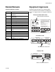
Related Manuals Related Manuals Equipment Approvals Component Manuals in English Equipment approvals appear on the following labels which are attached to the Fluid Station and EasyKey™. See FIG. 1 on page 4 and FIG. 2 on page 6 for label locations.
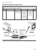
System Configuration and Part Numbers System Configuration and Part Numbers Wall Mount Fluid Station Configurator Key The configured part number for your equipment is printed on the equipment identification labels. See FIG. 1 for location of the identification labels. The part number includes one digit from each of the following six categories, depending on the configuration of your system.
System Configuration and Part Numbers Hazardous Location Approval Models using a G3000, G3000HR, or intrinsically safe Coriolis meter for both A and B meters are approved for installation in a Hazardous Location - Class I, Div I, Group D, T3 or Zone I Group IIA T3. Maximum Working Pressure Maximum working pressure rating is dependent on the fluid component options selected. The pressure rating is based on the rating of the lowest rated fluid component. Refer to the component pressure ratings below.
System Configuration and Part Numbers RoboMix Fluid Station Configurator Key The configured part number for your equipment is printed on the equipment identification labels. See FIG. 2 for location of the identification labels. The part number includes one digit from each of the following six categories, depending on the configuration of your system.
System Configuration and Part Numbers Hazardous Location Approval Models using a G250 or G250HR for both A and B meters are approved for installation in a Hazardous Location Class I, Div I, Group D, T3 or Zone I Group IIA T3. Maximum Working Pressure Maximum working pressure rating for RoboMix Systems is 190 psi (1.31 MPa, 13.1 bar). Check the identification label on the EasyKey or RoboMix fluid station for the system maximum working pressure. See FIG. 2.
Accessories Accessories Accessory 15V354 Third Purge Valve Kit 15V202 Third Purge Valve Kit 15V536 Solvent Flow Switch Kit 15V213 Power Cable, 100 ft (30.5 m) 15G710 Fiber Optic Cable, 100 ft (30.5 m) 15G614 Flow Control Extension Cable, 40 ft (12.
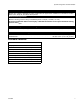
Warnings Warnings The following warnings are for the setup, use, grounding, maintenance, and repair of this equipment. The exclamation point symbol alerts you to a general warning and the hazard symbols refer to procedure-specific risks. When these symbols appear in the body of this manual, refer back to these Warnings. Product-specific hazard symbols and warnings not covered in this section may appear throughout the body of this manual where applicable.
Warnings WARNING SKIN INJECTION HAZARD High-pressure fluid from gun, hose leaks, or ruptured components will pierce skin. This may look like just a cut, but it is a serious injury that can result in amputation. Get immediate surgical treatment. • Tighten all fluid connections before operating the equipment. • Do not point gun at anyone or at any part of the body. • Do not put your hand over the spray tip. • Do not stop or deflect leaks with your hand, body, glove, or rag.
Important Two-Component Material Information Important Two-Component Material Information Isocyanate Conditions Spraying or dispensing materials containing isocyanates creates potentially harmful mists, vapors, and atomized particulates. Read material manufacturer’s warnings and material MSDS to know specific hazards and precautions related to isocyanates. Prevent inhalation of isocyanate mists, vapors, and atomized particulates by providing sufficient ventilation in the work area.
Glossary of Terms Glossary of Terms Air Chop - the process of mixing air and solvent together during the flush cycle to help clean the lines and reduce solvent usage. Air Chop Time- duration of each activation of the air purge valve during a chop sequence. User settable from 0.0-99.9 seconds. Analog - relating to, or being a device in which data are represented by continuously variable, measurable, physical quantities, such as length, width, voltage, or pressure.
Glossary of Terms Job Total - a resettable value that shows the amount of material dispensed through the system for one job. A job is complete when a color change or complete system flush occurs. K-factor - a value that refers to the amount of material that passes through a meter. The assigned value refers to an amount of material per pulse. Ki - refers to the degree fluid flow over shoots its set point. Kp - refers to the speed in which the fluid flow reaches its set point.
Overview Overview Usage The Graco ProMix 2KS is an electronic two-component paint proportioner. It can blend most two-component solvent and waterborne epoxy, polyurethane, and acid-catalyzed paints. It is not for use with “quick-setting” paints (those with a potlife of less than 15 minutes). • Color change options are available for low pressure • Can proportion at ratios from 0.1:1 to 50:1 in 0.1 (300 psi [2.1 MPa, 21 bar]) air spray and high presincrements.
Overview Table 1: Component Descriptions Component Flow Meters (MA, MB, MS) Description The following optional flow meters are available from Graco: • G3000 is a general purpose gear meter typically used in flow ranges of 75-3800 cc/min. (0.02–1.0 gal/min.), pressures up to 4000 psi (28 MPa, 276 bar), and viscosities of 20–3000 centipoise. The K-factor is approximately 0.119 cc/pulse. • G3000HR is a high resolution version of the G3000 meter. It is typically used in flow ranges of 38–1900 cc/min. (0.
Overview Wall Mount System Components EK ACV CCM PS* BCV MS FO* FC ST MA FM MB * See the ProMix 2KS Repair-Parts manual for optional cable lengths. TI12553a FIG. 3.
Overview DVA FI DVB MB MS MA RVB AT APV RVA SVA SM SVB SPV TI12556b FIG. 4.
Overview RoboMix System Components EK ACV CCM BCV Air Controls Purge Air PS* RoboMix Control Air FO* FC RS * See the ProMix 2KS Repair-Parts manual for optional cable lengths. TI12552a FIG. 5.
Overview Air Logic In Cable Path B Supply (1/4 npt) A Supply (1/4 npt) Ground Screw Air Purge Solvent Supply (1/4 npt) TI12511b A Dump Out B Dump Out Cover is removed for clarity MB DVB MA TI12579b DVA FIG.
EasyKey Display and Keyboard EasyKey Display and Keyboard Keypad LCD Display TI11630A Navigation Keys Alarm Reset Key FIG. 7. EasyKey Display and Keypad Display Shows graphical and text information related to setup and spray operations. Back light will turn off after 10 minutes without any key press. Press any key to turn back on. Keypad Used to input numerical data, enter setup screens, scroll through screens, and select setup values.
EasyKey Display and Keyboard Fiber Optic Strain Relief Port Audible Alarm AC Power Switch Main Power Access Port Ground Screw I/S Power Graco Web Interface Discrete I/O Cable Connector Ports TI12638a TI12657a FIG. 8. EasyKey Connections and AC Power Switch AC Power Switch Graco Web Interface Port Turns system AC power on or off. Used to communicate with the ProMix from a PC to: I/S Power Power circuit to Fluid Station.
Run Mode Screens Run Mode Screens NOTE: See FIG. 11 for a map of the Run screens. Detailed screen descriptions follow. . Splash Screen At power up, the Graco logo and software revision will display for approximately 5 seconds, followed by the Status Screen (see page 24). FIG. 9. Splash Screen The Splash screen will also momentarily display “Establishing Communication.
Run Mode Screens Press the Setup key to enter Setup mode. TI12802a FIG. 11.
Run Mode Screens Status Screen 6 Target Flow Rate and Current Flow Rate: in cc/min. • Use the Up or Down Run screens. • Press the Setup keys to scroll through the 7 Animation: when the gun is triggered, the gun appears to spray and the component A or B hose lights up, showing which component dose valve is open. key to enter the Setup screens from the Status screen. • 8 Current Date and Time The other keys have no function in this Status screen.
Run Mode Screens Manual Override Screen Flow Rate Range This screen displays the flow rate range selected on Advanced Setup Screen 5 (see page 41). Flow Set Point The Flow Set Point is user settable. If Flow Control Override is set to “Off” or “Pressure” in Advanced Setup Screen 1 on page 39, the Flow Set Point will display as cc/min. Enter the desired flow set point within the range. FIG. 13. Manual Override Screen If Flow Control Override is set to “% Open,” the Flow Set Point will display as % Open.
Run Mode Screens Global Flow Control Data Copy Reset Total Screen This field allows you to copy flow control data from the active recipe to all recipes. Press the Enter key to view the menu, then select Start or Abort. See FIG. 16. FIG. 18. Reset Total Screen FIG. 16. Global FC Data Copy Totals Screen If job is reset, job number will increment by one for default. Reset Solvent Screen FIG. 17. Totals Screen FIG. 19.
Run Mode Screens Alarms Screen See FIG. 22. If the tank volume reaches the low-level threshold, the EasyKey screen will display the Tank Level Low alarm and prompt the user to do one of the following: 1. Refill tank volume to clear the alarm. 2. Resume mixing by selecting “Spray 25% of Remainder.” If this selection is chosen, a second alarm will occur after 25% of the remaining volume is mixed. Refill tank volume to clear the alarm. FIG. 20. Alarms Screen Two screens show the last 10 alarms.
Setup Mode Setup Mode Press the Setup key to enter Setup mode. NOTE: See FIG. 23 for a map of the Setup screens. Detailed screen descriptions follow. Press the Setup key to enter Setup mode. This screen appears only if a password is activated. To access Advanced Setup Screens, page 38 and Recipe Setup Screens, page To access System Configuration Screens, page 31. Press the Setup key to exit Setup mode and return to the Status screen. This screen appears momentarily if a password is activated.
Setup Mode Password Screen Set Up Home Screen If a password has been activated (see Configure Screen 1, page 32), the Password screen will appear. You must enter the password to access the Set Up Home Screen. Entering the wrong password returns the display to the Status Screen. NOTE: If you forget the password, you can reset the password (to 0), using the ProMix Web Interface (see manual 313386). FIG. 26. Set Up Home Screen This screen displays when you enter Setup mode.
Setup Mode Table 3: Component Software Versions Component Display (may vary from examples shown) Description EK (EasyKey) 2.00.012 EasyKey software version. FP (Fluid Plate) 2.00.012 Fluid Plate software version. BC (Booth Control) -.- Booth Control not installed, not detected, or not operational. 1.XX Booth Control software version 1.00 or 1.01. 2.XX Booth Control software version 2.XX. -.- Color Change Module 1/2 not installed, not detected, or not operational. 1.
Setup Mode System Configuration Screens NOTE: See FIG. 27 for a map of the System Configuration Screens. Detailed screen descriptions follow. NOTE: Each screen displays the current screen number and the total number of screens in the group. TI12804a FIG. 27.
Setup Mode Configure Screen 1 Configure Screen 2 FIG. 28. Configure Screen 1 FIG. 29. Configure Screen 2 Language Month Defines the language of the screen text. Select English (default), Spanish, French, German, Italian, Dutch, Japanese (Kanji), Korean, and Chinese (Simplified). Enter current month. Password Day Enter current day. The password is only used to enter Setup mode. The default is 0, which means no password is required to enter Setup.
Setup Mode Configure Screen 3 FIG. 30. Configure Screen 3 Run Mode Select the Run mode application from the pulldown menu: Automatic (default), Semi-Automatic (uses a manual spray gun), or Manual. NOTE: ProControl 1KS is also available as a selection. For further information, see ProControl 1KS operation manual 3A1080. Dump Valve A This field only appears if the system includes an optional dump valve A. If dump valve A is included, set to On. Configure Screen 4 FIG. 31.
Setup Mode DD Setup Mode Configure Screen 5 See FIG. 32 and FIG. 33. Selecting “DD” makes the Dynamic Dosing Setup mode field appear. Select On to enable DD setup mode, or Off to disable. See page 86 for further information. FIG. 34. Configure Screen 5 Flow Control FIG. 32. Configure Screen 4, dynamic dosing selected This field only appears if Run Mode is set to “Automatic” in Configure Screen 3, page 33. Select On or Off. If set to “On,” Advanced Setup Screen 5, page 41 is added.
Setup Mode Configure Screen 6 FIG. 35. Configure Screen 6 (Automatic mode shown) Flow Control This field only appears if Run Mode is set to “Automatic” in Configure Screen 3, page 33 and Flow Control is set to “On” in Configure Screen 5, page 34. Select “Discrete” or “Network.” Proportioning Select “Discrete” or “Network.” Gun 1 Trigger Select “Discrete” or “Network” if Run Mode is set to “Automatic” in Configure Screen 3, page 33.
Setup Mode Option Screens Verification Screen NOTE: See FIG. 27 on page 31 for a map of the Option Screens. Detailed screen descriptions follow. NOTE: Each screen displays the current screen number and the total number of screens in the group. Option Screen 1 FIG. 37. Verification Screen Verification This screen appears if Flush and Fill Input or K-factor Input are changed from “Recipe” to “Global” in Option Screen 1. FIG. 36.
Setup Mode Option Screen 2 FIG. 38. Option Screen 2 External Color Change If set to “Off”, Color/Catalyst Purge Time and Color/Catalyst Fill Time appear in Advanced Setup Screen 1, page 39 or Recipe Setup Screen 2, page 44 (depending on whether Flush and Fill Inputs are set to “Global” or “Recipe”). If set to “On”, these fields are removed from the screens. Auto Dump If the auto dump feature is being used, set to “On”.
Setup Mode Advanced Setup Screens NOTE: See FIG. 39 for a map of the Advanced Setup Screens. Detailed screen descriptions follow. Advanced Setup screens 2, 3, 4, and 8 appear depending on selections made in Option screens 1 and 2. Screen 5 appears if Flow Control is set to “On” in Configure screen 5. TI12805a FIG. 39.
Setup Mode NOTE: Each screen displays the current screen number and the total number of screens in the group. The total number of screens in a group and the fields displayed on each screen may vary depending on selections made in the System Configuration Screens and Option Screens. Manual Override Advanced Setup Screen 1 Gun 1/Gun2 Potlife Volume This field only appears if Run Mode is set to “Automatic” or “Semi-automatic” in Configure Screen 3, page 33. Set to “On” to override all outside control.
Setup Mode Advanced Setup Screen 2 Advanced Setup Screen 3 FIG. 42. Advanced Setup Screen 2 FIG. 43. Advanced Setup Screen 3 This screen appears only if Flush and Fill Input is set to “Global” in Option Screen 1, page 36. This screen appears only if Flush and Fill Input is set to “Global” in Option Screen 1, page 36. First Purge Source Select “Air,” “Solvent,” or “3rd Flush Valve” (available only if 3rd Flush Valve is set to “On” in Configure Screen 3 on page 33).
Setup Mode Advanced Setup Screen 4 Advanced Setup Screen 5 FIG. 44. Advanced Setup Screen 4 FIG. 45. Advanced Setup Screen 5 (Automatic Mode with Flow Control Only) This screen appears only if K-factor Input is set to “Global” in Option Screen 1, page 36. This screen appears only if Flow Control is set to “On” in Configure Screen 5, page 34. K-factor A Meter Flow Rate Range Enter the k-factor (cc/pulse) for flow meter A.
Setup Mode Advanced Setup Screen 6 FIG. 46. Advanced Setup Screen 6 This screen shows the status of recipe analog inputs and digital outputs. If box is shaded the input recipe is active. Advanced Setup Screen 7 Advanced Setup Screen 8 FIG. 48. Advanced Setup Screen 8 This screen appears only if Flush and Fill Input is set to “Global” in Option Screen 1, page 36 and Special Outputs is set to 1, 2, 3, or 4 in Configure Screen 5, page 34. The I/O board has four programmable outputs. FIG. 47.
Setup Mode Recipe Setup Screens NOTE: See FIG. 49 for a map of the Recipe screens. Detailed screen descriptions follow. Recipe 0 Screens Recipe screens 3, 4, 5, 6, and 7 appear depending on selections made in Option screens 1 and 2 TI12806a FIG.
Setup Mode NOTE: Each screen displays the current screen number and the total number of screens in the group. The total number of screens in a group and the fields displayed on each screen may vary depending on selections made in the System Configuration Screens and Option Screens. Recipe Setup Screen 2 Recipe Setup Screen 1 FIG. 51. Recipe Setup Screen 2 FIG. 50. Recipe Setup Screen 1 Ratio Enter the mix ratio of component A over component B (0.0:1 to 50:1).
Setup Mode Recipe Setup Screen 3 Recipe Setup Screen 4 FIG. 52. Recipe Setup Screen 3 FIG. 53. Recipe Setup Screen 4 This screen appears only if Flush and Fill Input is set to “Recipe” in Option Screen 1, page 36. This screen appears only if Flush and Fill Input is set to “Recipe” in Option Screen 1, page 36. First Purge Source If Number of Guns is set to “2” in Configure Screen 4, page 33, a Gun 2 column will appear in this screen.
Setup Mode Recipe Setup Screen 5 FIG. 54. Recipe Setup Screen 5 This screen appears only if K-factor Input is set to “Recipe” in Option Screen 1, page 36. K-factor A Meter Enter the k-factor (cc/pulse) for flow meter A. This is the amount of material that passes through the flow meter per pulse (electrical pulse signal). K-factor B Meter Enter the k-factor (cc/pulse) for flow meter B. Recipe Setup Screen 6 FIG. 55.
Setup Mode Recipe 0 Screens NOTE: See FIG. 49 on page 43 for a map of the Recipe 0 screens. Detailed screen descriptions follow. Recipe 0 is typically used: • in multiple color systems to purge out material lines without loading a new color • at the end of a shift to prevent hardening of catalyzed material. NOTE: Each screen displays the current screen number and the total number of screens in the group.
Setup Mode Recipe 0 Screen 3 Recipe 0 Screen 4 FIG. 60. Recipe 0 Screen 4 FIG. 59. Recipe 0 Screen 3 This screen only appears if Solvent Monitor is set to “Meter” in Configure Screen 5, page 34 and Flush Volume Check is set to “On” in Option Screen 1, page 36 or 3rd Flush Valve is set to “On” in Configure Screen 3 on page 33. This screen appears only if Flush and Fill Input is set to “Recipe” in Option Screen 1, page 36 and Special Outputs is set to 1, 2, 3, or 4 in Configure Screen 5, page 34.
Setup Mode Calibration Screen FIG. 61. Calibration Screen Use this screen to calibrate a meter. Set to “Meter A,” “Meter B,” or “Solvent Meter” (available if Solvent Monitor in Configure Screen 5, page 34, is set to “Meter”). • Start - start calibration • Abort - stop calibration • Purge - purge sampling valves after calibration See Meter Calibration, page 100, for when and how to calibrate meter.
Setup Mode 50 312779E
ProMix 2KS Integration Specifics ProMix 2KS Integration Specifics Discrete I/O vs Network Communications The ProMix 2KS Automatic system does not use a Booth Control. Instead, it uses Discrete I/O or Network Communications to drive the system. Each method can be used exclusively, or both at the same time.
ProMix 2KS Integration Specifics Digital Inputs See Automation Flow Charts, pages 55-59. Mix Start: This is a maintained input. When High, the ProMix 2KS will attempt to enter Mix mode. This Mix Start input should not be attempted unless the Mix_Ready output is recognized. This ensures that there are no alarms and that the Mix Start input is appropriate. This input stays High at all times when mixing on demand is required.
Digital Output Common/Power Special Output #1 Special Output #2 Special Output #3 Digital Output Common/Power Special Output #4 ProMix 2KS Integration Specifics JLS Digital Output Common/Power Flow Rate Alarm Output Flow Control Calibrate Active Fill Active Mix Ready Output Mix Active Output Purge/Recipe Change Active Output Digital Output Common/Power Recipe Change Input Recipe Bit 5 Input Recipe Bit 4 Input Recipe Bit 3 Input Recipe Bit 2 Input Recipe Bit 1 Input Recipe Bit 0 Input Digital Input
ProMix 2KS Integration Specifics Digital Outputs Analog Inputs See Automation Flow Charts, pages 55-59. Purge_CC_Active: This output will remain High during the manual Purge or Color Change purge sequence. See the Color Change Charts (FIG. 109-FIG. 126) for further information. Flow Command: This is the positive side of the 0 – 10 Vdc signal. (See Common under Digital Inputs, page 52.) This input corresponds to the Flow Range setting in Advanced Setup Screen 5, page 41.
ProMix 2KS Integration Specifics Automation Flow Charts Start Mix Mode Process See FIG. 65, Table 5, and Table 6. Start Mix Mode Process NO YES Is Mix Ready bit = 1? Must be Alarm Condition or Active Recipe 61. See Alarm Processing on page 59, or Startup from Recipe 61 (see NOTE Set Mix bit = 1 NO NOTE: At power up the system defaults to Recipe 61, which is not a valid recipe number. Initiate a color change to Recipe 0 or a valid recipe number (1-60).
ProMix 2KS Integration Specifics Mixing Mode Process See FIG. 66, Table 5, and Table 6. Mixing Mode Process Mixing Mode is desired. PLC is polling to ensure Mixing Mode is maintained. NO Is Mix Active bit = 1? YES Mixing Process active Check Alarm Condition: is Alarm_ General bit = 1? NO Go to Start Mix Mode Process, page 55 YES Go to Alarm Processing, page 59 FIG. 66.
ProMix 2KS Integration Specifics Purge Mode Process See FIG. 67, Table 5, and Table 6. Start NO Is Mix Ready bit = 1? Must be Alarm Condition or Active Recipe 61. See Alarm Processing on page 59, or Startup from Recipe 61 (see NOTE below). Set Purge bit = 1? NO NO (Wait for Mix Ready) Is Mix Ready bit = 1? NOTE: At power up the system defaults to Recipe 61, which is not a valid recipe number. Initiate a color change to Recipe 0 or a valid recipe number (1-60).
ProMix 2KS Integration Specifics Color Change Mode Process See FIG. 68, Table 5, and Table 6. Color Change Process (basic) Do nothing. Spraying at desired recipe. YES Is Active Recipe = to desired recipe? (Register 40005). NO Load ccNewRecipe (Register 40046) with recipe number to Color Change to (0 through 60 is valid). Ensure ColorChange bit is seen by ProMix 2KS Is Purge_CC_Active bit = 1? NO YES Set ColorChange (CC) bit = 1. Clear ColorChange (CC) bit (momentary input). CC process started.
ProMix 2KS Integration Specifics Alarm Processing See FIG. 69, Table 5, Table 6, and Table 7. Alarm Processing An Alarm Condition has been found previously. Alarm_General = 1. Check if Potlife Alarm: is Alarm_ Potlife bit = 1? NO Two options: Determine the exact alarm from Table 7 on page 62 and solve what caused the alarm, as required. • Purge or Color Change to remove mixed material in the line. • Place in Mix mode and spray the Potlife Volume set in the ProMix 2KS.
ProMix 2KS Integration Specifics Table 5: ProMix 2KS Digital Inputs (Modbus Register 40040) Bit Digital Input Binary Name Details 0:5 0 0 0 0 0 0 0 0 0 0 X X X X X X Recipe Binary bits for viewing discrete inputs only.
ProMix 2KS Integration Specifics Table 6: ProMix 2KS Digital Outputs (Modbus Register 40041) Bit Digital Input Binary Name Details 0 0 0 0 0 0 0 0 0 0 0 0 0 0 0 0 1 Purge_CC_Active “1” indicates Purge or Color Change is in progress 1 0 0 0 0 0 0 0 0 0 0 0 0 0 0 1 0 Mix_Active “1” indicates Mix is in progress 2 0 0 0 0 0 0 0 0 0 0 0 0 0 1 0 0 Mix_Ready “1” indicates No Alarms and OK to Mix 3 0 0 0 0 0 0 0 0 0 0 0 0 1 0 0 0 CC_Fill_Active “1” indicates the Fill portion of a Color Change is in
ProMix 2KS Integration Specifics Table 7: ProMix 2KS Active Alarms (Modbus Register 40010) 62 Bit Digital Input Binary Name Details Low Byte: 0 0000 0000 0000 0000 No Bits Set No Active Alarms Low Byte: 0 0000 0000 0000 0001 Comm_Error Low Byte: 0 0000 0000 0000 0010 Potlife_Alarm Low Byte: 0 0000 0000 0000 0100 Ratio_High_Alarm Low Byte: 0 0000 0000 0000 1000 Ratio_Low_Alarm Low Byte: 0 0000 0000 0001 0000 Overdose_A_Alarm Low Byte: 0 0000 0000 0010 0000 Overdose_B_Alarm Low By
ProMix 2KS Integration Specifics ProMix 2KS EasyKey Digital Input PLC Output (Sourcing) Input Common Output Input 24 Vdc Common PLC Input (Sinking) ProMix 2KS EasyKey Digital Output 24 Vdc Output Common Input Output Common ProMix 2KS EasyKey Digital Output PLC Input (Sourcing) Output Common Output Input 24 Vdc Common FIG. 70.
ProMix 2KS Integration Specifics Table 8: Discrete I/O Terminal Connections Terminal Terminal Location Name Details (also see pages 60 and 61) Digital Inputs 1 J2, Remote I/O Board Mix Set Bit to Initiate Mix Mode (maintain) 2 J2, Remote I/O Board Purge Set Bit to “1” to initiate Purge Sequence (maintained) 3 J2, Remote I/O Board Job_Complete Set Bit to “1” to initiate Job Complete Input (momentary) 4 J2, Remote I/O Board External CC Ready Set Bit to “1” to initiate External Color Change
ProMix 2KS Integration Specifics Table 8: Discrete I/O Terminal Connections Terminal Terminal Location Name Details (also see pages 60 and 61) Digital Outputs 1★ J4, Remote I/O Board Digital Output Common/Power 2 J4, Remote I/O Board Purge_CC Active “1” Indicates Purge or Color Change is in progress 3 J4, Remote I/O Board Mix_Active “1” Indicates Mix is in progress 4 J4, Remote I/O Board Mix_Ready “1” Indicates No Alarms and OK to Mix 5 J4, Remote I/O Board CC_Fill_Active “1” Indicate
ProMix 2KS Integration Specifics Table 9: ProMix 2KS Recipe Bits Recipe Bits 5 0 0 0 0 0 0 0 0 0 0 0 0 0 0 0 0 0 0 0 0 0 0 0 0 0 0 0 0 0 0 0 0 1 66 4 0 0 0 0 0 0 0 0 0 0 0 0 0 0 0 0 1 1 1 1 1 1 1 1 1 1 1 1 1 1 1 1 0 3 0 0 0 0 0 0 0 0 1 1 1 1 1 1 1 1 0 0 0 0 0 0 0 0 1 1 1 1 1 1 1 1 0 2 0 0 0 0 1 1 1 1 0 0 0 0 1 1 1 1 0 0 0 0 1 1 1 1 0 0 0 0 1 1 1 1 0 Number 1 0 0 1 1 0 0 1 1 0 0 1 1 0 0 1 1 0 0 1 1 0 0 1 1 0 0 1 1 0 0 1 1 0 0 0 1 0 1 0 1 0 1 0 1 0 1 0 1 0 1 0 1 0 1 0 1 0 1 0 1 0 1 0 1 0 1 0 0 1 2 3 4
Integrated Flow Control Integrated Flow Control Flow Control Description Flow control is an optional feature which incorporates an intrinsically safe regulator control module with the ProMix 2KS automatic system. Flow control precisely regulates the flow of material to a manual or automatic air spray gun, to help ensure adequate coverage and avoid sags or runs in the finish coat. NOTE: Flow control cannot be selected with dynamic dosing. It is not for use with air-assisted or airless spray guns.
Integrated Flow Control Fluid and Air Pressure Requirements The fluid input pressure to the fluid regulator must be high enough to provide a 15-20 psi (0.1-0.14 MPa, 1.0-1.4 bar) pressure differential across the regulator at the highest flow setting. For example, if the maximum flow rate set point is 280 cc/min and 35 psi outlet pressure is required to achieve that flow, the input pressure must be 50-55 psi. Required air pressure to the flow control module is 70-100 psi (0.35-0.7 MPa, 3.5-7.0 bar).
Integrated Flow Control Flow Input: Feedback from Meters A and B Air-operated Fluid Regulator Mixed Material Line Fluid Pressure Sensor Meter B Fluid Control Board Meter A Air Signal to Regulator Analog Signal to V/P Air Line V/P (Voltage/Air Pressure) Valve Pressure Input: Feedback from Fluid Pressure Sensor TI17118a FIG. 73.
Integrated Flow Control Flow Control Operating Process Example Operating Ranges Step 2: Pressure Loop Flow Control operating ranges correlate the desired flow rate to the incoming flow set point signal (see below). The operating ranges are: NOTE: The gun must be triggered during the pressure loop. • • • • 0-300 cc/min 0-600 cc/min 0-1200 cc/min 0-100% (% open in manual override mode) In this example, the range is set to 0-300 cc/min and the target flow rate is 150 cc/min.
Integrated Flow Control Step 3: Flow Input Fluid Pressure Sensor Step 1: ProMix 2KS receives a flow rate setpoint from PLC/robot Analog Signal to V/P Air Line V/P (Voltage/Air Pressure) Valve Step 2: Pressure Input TI17118a FIG. 75.
Integrated Flow Control Flow Control Setup Flow Control Startup 1. Install the intrinsically safe flow regulator (FC) as explained in the ProMix 2KS Installation Manual. 1. Set Flow Control to “On” in Configure Screen 5. 2. Ensure that the analog signal is 0-10 Vdc, or is properly provided through network communication. 3. Calibrate the system’s flow meters; see page 100. This ensures that the K-factors are tuned to the range of materials being used. 4. Verify that the I/O inputs are working properly.
Integrated Flow Control 3. Set Flow Control Override to % Open. See FIG. 79 and Table 10. On the Manual Override Screen, the Flow Set Point field will display as a percentage open (see FIG. 80). 4. On the Manual Override Screen, drive the regulator to a percentage open that starts fluid flow. Fluid pressure should be above 12 psi (.08 MPa, 0.84 bar) [see the Status Screen]. Observe the fluid flow rate at this pressure. This is the achievable low end flow rate for the system’s given restriction.
Integrated Flow Control Flow Control Calibration Flow Control Calibration is an automatic routine that establishes a pressure vs flow profile between low and high operating points. See FIG. 86. The profile may be unique to each recipe or may be globally copied to all recipes. 3. Go to Advanced Setup Screen 1 (see FIG. 83). Turn Manual Override On. . NOTE: Calibration cannot be done in recipe 0 or 61. 1. Load a color. 2. Go to Advanced Setup Screen 5 (see FIG. 82).
Integrated Flow Control 5. Return to the Status Screen (see FIG. 85). The status bar at the bottom of the screen will indicate that Mix Calibration is in progress. 8. When calibration is complete, the Status Screen will change from Mix Calibration to Mix. The unit should have built a complete table for the flow rate range selected in step 2. NOTE: If the voltage reached 3.
Integrated Flow Control Global FC Data Copy Setting Ki and Kp Set Global FC Data Copy to Start on the Manual Override Screen (see FIG. 87). Global copy provides a starting point for all recipes, enabling Continuous Learning (see page 76) to take over. FIG. 89 shows the definition and relationship between Ki and Kp. Global copy works very well with multiple colors when the viscosities are similar.
Integrated Flow Control Pressure Flow Control Mode When the Flow Control Override is set to “Pressure”, the system will only drive to the pressure associated with the flow rate request of the saved calibration table. It will not close the loop with the flow meters. This mode may be used with a ProMix 2KS connected both to a robot with flow control and to a manual gun. Because there are two flow paths, the meters cannot be used to close the flow loop. Therefore the robot can run a calibration by itself.
Integrated Flow Control Flow Control Troubleshooting Problem: Flow Command does not produce fluid output. Test the system as follows, to determine if the problem is mechanical or electrical. 1. Install a 0-100 psi (0-0.7 MPa, 0-7.0 bar), 1/8 npt(m) air pressure gauge (not supplied) as follows. a. For module 249849: Remove the plug from the 1/8 npt(f) air gauge port and install the gauge. See FIG. 71 on page 67. b. For module 24H989: Install a 1/8 npt(m) x 1/8 npt (fbe) tee in the air outlet port.
Integrated Flow Control Result of the Test Gauge reading increases and decreases as % Open value is changed and fluid flow does not change or is not present. Gauge reading does not increase and decrease as % Open value is changed. Cause Solution The problem is mechanical: 1. Clear any clogs. • restriction/plugged hose 2. Remove restrictions. • plugged gun tip 3. Clean and/or repair fluid regulator.
System Operation System Operation Operation Modes Mix System mixes and dispenses material (apply Mix input). Standby Stops the system (remove Mix input). Purge Purges the system, using air and solvent (apply Purge input). Sequential Dosing Components A and B dispense sequentially in the necessary volumes to attain the mix ratio. Dynamic Dosing In typical operation (ratios 1:1 and above), component A dispenses constantly.
System Operation Typical PLC Interaction with ProMix 2KS This section describes a typical interaction when a local PLC is directly connected to the Discrete I/O connections of the ProMix 2KS. See ProMix 2KS Integration Specifics on page 51 for a detailed explanation of inputs and outputs. NOTE: Communications fields of Configure Screen 6 must be set to DISCRETE (see page 35).
System Operation Alarm Monitoring/Reset (Discrete I/O) Anytime an alarm occurs, the Alarm Reset input will reset the alarms and allow for processing of the next step by automation, except for the following conditions: • key. Only a Purge/Color Change or spraying the Potlife volume will reset a Potlife alarm. (See Alarm_Potlife output information on page 54.) • ProMix 2KS has four specials that can each be turned off and on twice throughout a color change sequence.
System Operation General Operating Cycle, Sequential Dosing d. Dose Valve B (DVB) opens, and fluid flows into the integrator and is aligned proportionately with component A. 1. The system enters and loads the desired color. e. Flow Meter B (MB) monitors the fluid volume dispensed and sends electrical pulses to the ProMix 2KS controller. 2. The system enters Mix mode to begin operation. 3. The ProMix 2KS controller sends signals to activate the solenoid valves.
System Operation DVA DVB FI MB MS MA RVB AT APV RVA TI12556b SVA SM SVB SPV Key: MA DVA RVA SVA MB DVB RVB Component A Meter Component A Dose Valve Component A Sampling Valve Component A Shutoff Valve Component B Meter Component B Dose Valve Component B Sampling Valve SVB MS SPV APV SM FI AT Component B Shutoff Valve Solvent Meter (accessory) Solvent Purge Valve Air Purge Valve Static Mixer Fluid Integrator Air Purge Valve Air Supply Tube FIG. 91.
System Operation General Operating Cycle, Dynamic Dosing Overview Dynamic Dosing System Parameters Dynamic Dosing provides on-demand proportioning, eliminating the need for an integrator and therefore minimizing undesired material contact. This feature is especially useful with shear-sensitive and waterborne materials. The following parameters affect dynamic dosing performance: A restrictor injects component B into a continuous stream of component A.
System Operation Select a Component B Restrictor Size Install the 15U955 Injection Kit in the fluid manifold as explained in the ProMix 2KS Installation manual. Use the charts provided in that manual to select an appropriate restrictor size based on the desired flow and mix ratio. NOTE: Do not use the material mixed when in DD setup mode, as it may not be on ratio due to the disabled alarms. Turn On Dynamic Dosing 1. On the EasyKey press the Setup 3.
System Operation Balancing A/B Pressure If component B pressure is too high, it will push the component A stream aside during B injection. The valve will not open long enough, causing a High Ratio alarm. If component B pressure is too low, it will not be injected in sufficient volume. The valve will stay open too long, causing a Low Ratio alarm.
System Operation Table 12: Dynamic Dosing Troubleshooting Guide (for complete system troubleshooting, see Table 17 beginning on page 116) Warning/Alarm Message Solution B Pressure Too Low (see FIG. 96) • • • Increase B pressure. Clean restrictor or use a larger size. Verify B valve is opening properly. B Pressure Too High • • Increase A pressure or decrease B pressure. Use a smaller restrictor. Off Ratio Low • • Increase A pressure or decrease B pressure. Use a smaller restrictor.
System Operation Start Up 1. Go through the Pre-Operation Checklist in Table 14. Table 14: Pre-Operation Checklist ✓ Checklist System grounded Verify all grounding connections were made. See the Installation manual. ➜ Graco logo, software revision, and “Establishing Communication” will display, followed by Status screen. See page 22. ➜ At power up the system defaults to Recipe 61, which is not a valid recipe number. Initiate a color change to Recipe 0 or a valid recipe number (1-60).
System Operation 10. Purge air from the fluid lines. a. Shut off air to the gun by closing the air regulator or shutoff valve for the gun atomizing air. b. Trigger the gun (manual or automatic) into a grounded metal pail. c. Manual gun shown If the fluid flow rate is too low: increase air pressure to component A and B fluid supplies or increase the regulated fluid pressure.
System Operation Shutdown Pressure Relief Procedure Overnight Shutdown NOTE: The following procedures relieve all fluid and air pressure in the ProMix 2KS system. Use the procedure appropriate for your system configuration. 1. Leave the power on. 2. Run Recipe 0 to purge solvent through meters and gun. Service Shutdown 1. Follow Pressure Relief Procedure on page 91. 2. Close main air shutoff valve on air supply line and on ProMix 2KS. 3. Shut off ProMix 2KS power (0 position). FIG. 103. 4.
System Operation Systems with Color Change and without Dump Valves Systems with Color/Catalyst Change and Dump Valves NOTE: This procedure relieves pressure through the sampling valve. NOTE: This procedure relieves pressure through the dump valves. 1. Complete all steps under Single Color Systems, page 91. 1. Complete all steps under Single Color Systems, page 91. 2. Close the A side shutoff valve (SVA), FIG. 106. Open the A side sampling valve (RVA). 2.
System Operation Dose Valve B Override Button RoboMix Fluid Station Dose Valve A Override Button TI12655a Wall Mount Fluid Station F2 F1 J1 Power Fiber Optic CAN J13 CAN J12 1 J14 1 J15 GFB 2 GFB 1 Dump B J9 Dump A 1 Purge B Dose A Dose B Purge A Valve Overrides 3rd Purge J3 1 J8 Dump Valve A Dump Valve B GFB 1 Optional Solenoid Locations GFB 2 3rd Purge Valve Solenoid Dose Valve A Solenoid Dose Valve B Solenoid Purge Valve A Solenoid Purge Valve B Solenoid TI12652b FIG.
System Operation Color Solenoid Identification Label Catalyst Color Solenoid Identification Label TI12826a Solvent Solenoid Overrides FIG.
System Operation Purging Read Warnings, page 9. Follow the Grounding instructions in your system Installation manual. To avoid splashing fluid in the eyes, wear eye protection. There are 4 purging procedures in this manual: • • • • 2. Set the solvent supply pressure regulator at a pressure high enough to completely purge the system in a reasonable amount of time but low enough to avoid splashing or an injection injury. Generally, a setting of 100 psi (0.7 MPa, 7 bar) is sufficient. 3.
System Operation Purging Using Recipe 0 Purging Fluid Supply System Recipe 0 is typically used: • in multiple color systems to purge out material lines without loading a new color • at the end of a shift to prevent hardening of catalyzed material. Follow this procedure before: • the first time material is loaded into equipment* • servicing • shutting down equipment for an extended period of time • putting equipment into storage To setup Recipe 0, go to Advanced Setup.
System Operation 3. Adjust the solvent fluid supply pressure. Use the lowest possible pressure to avoid splashing. 4. Remove the Fluid Station cover to access the solenoid valves. See FIG. 104 on page 93. 5. Purge as follows: • Single color/single catalyst systems: Purge component A side. Press the manual override on the Dose Valve A solenoid valve and trigger the gun into a grounded metal pail. Purge component B side.
System Operation Purging Sampling Valves and Tubes Follow this procedure after meter calibration. 1. Go to Standby mode (remove Mix input). 2. See FIG. 106, page 94. Close both fluid shutoff valves and sampling valves. 3. Route the sampling tubes into a grounded waste container. 4. On a single color system, attach a solvent supply line to Flow Meter A inlet. 5. On the EasyKey, press Setup key and access the Advanced Setup screens. 6. Press the Right Arrow key to select the Calibra- tion screen.
System Operation Solvent Push Feature The Solvent Push feature enables the user to save some mixed material by pushing it out to the gun with solvent. The quantity saved is 50% of the potlife volume entered in Advanced Setup Screen 1 on page 39. If there are 2 guns, the smaller potlife volume is used. 4. The system will dispense solvent to push the mixed material out to the gun. The Booth Control display alternately shows dashes and the percent remaining (0-99%) of the 50% of the potlife volume.
Meter Calibration Meter Calibration 4. Place the beakers (minimum size - 250 cc) in holders. Put the sampling tubes into the beakers. (Wall Mount Fluid Station only.) To avoid splashing fluid in the eyes, wear eye protection. The fluid shutoff valves and ratio check valves are retained by mechanical stops that prevent accidental removal of the valve stem while the manifold is pressurized.
Meter Calibration 8. Dispense component A or B into beaker. 12. After the volume for A, B, or Solvent is entered, the ProMix 2KS controller calculates the new flow meter K-factor and shows it on the Calibration Screen. a. To avoid splashing, slowly open sampling valves. b. For more accurate calibration, adjust the valve to dispense at a flow rate similar to your production spray flow rate. c.
Color Change Color Change Color Change Procedures Multiple Color Systems 1. Shut off air to the gun. 2. Place the gun in the gun flush box if used, and close the lid. 3. Go to Standby mode (remove Mix input). 4. Select the new recipe. Begin the color change sequence. 5. If a gun flush box is not used, trigger the gun (manual or automatic) into a grounded metal pail until the color change sequence is complete. Color Change Sequences FIG. 109 through FIG. 126 illustrate various color change sequences.
Color Change Color Purge/Dump Step P0-P1 • This sequence flushes out the color with solvent, from the color valve to the Dump A valve. • The color change solvent valve and the Dump A valve open during the Purge Time. • The color change solvent valve closes when the Purge Time expires. Color Fill Step P1-P2 • This sequence fills the line with the new color all the way to the Dump A valve. • The new color valve and the Dump A valve open during the Fill Time.
Color Change Table 15: Color Change Chart Reference Number of Gun Flush Boxes Refer to Fig. Starting Recipe Ending Recipe Color Change Catalyst Change Dump Valves 3rd Purge Valve X X Yes Yes Yes Yes 0 FIG. 110 X X Yes Yes Yes No 0 FIG. 109 X X Yes No No No 0 FIG. 112 X X Yes No Yes No 0, 1, or 2 FIG. 111 X X No Yes Yes No 0, 1, or 2 FIG. 113 X X No No No No 0, 1, or 2 FIG. 123 X X Yes Yes Yes No 1 FIG. 115 X X Yes No No No 1 FIG.
Color Change ProMix 2KS Recipe Change Chart 1: A1 to A2, B1 to B2 with Dump Valves Valve Time-Sequence A Dump A Dump B B Color Change Solvent Catalyst Change Solvent Color Change A Catalyst Change B A B A B P0 P1 P2 P3 P4 Color Purge Time P0->P1 Color Fill Time P1->P2 Catalyst Purge Time P2->P3 Catalyst Fill Time P3->P4 CC Purge/Fill Timers are independent of Mixed Material Purge Timers. This line defines when the Mixed Fill Time begins.
Color Change ProMix 2KS Recipe Change Chart 3: A1 to A2, same B with Dump Valves Valve Time-Sequence A Dump A Dump B Color Change Solvent Catalyst Change Solvent Color Change A Catalyst Change B A P0 A B P1 P2 P3 P4 Color Purge Time P0->P1 Color Fill Time P1->P2 CC Purge/Fill Timers are independent of Mixed Material Purge Timers. This line defines when the Mixed Fill Time begins. The longer of the two timers defines when the Mixed Fill Time begins.
Color Change ProMix 2KS Recipe Change Chart 5: B1 to B2, same A with Dump Valves Valve Time-Sequence Dump A Dump B B Color Change Solvent Catalyst Change Solvent Color Change A Catalyst Change B A B B P0 P1 P2 P3 P4 Catalyst Purge Time P0->P1 Catalyst Fill Time P1->P2 CC Purge/Fill Timers are independent of Mixed Material Purge Timers. This line defines when the Mixed Fill Time begins. The longer of the two timers defines when the Mixed Fill Time begins.
Color Change ProMix 2KS Recipe Change Chart 7: A1 to A2, B1 to B2 with Dump Valves, 1 GFB Valve Time-Sequence A Dump A Dump B B Color Change Solvent Catalyst Change Solvent Color Change A Catalyst Change B A A B B P0 P1 P2 P3 P4 Color Purge Time P0->P1 Color Fill Time P1->P2 Catalyst Purge Time P2->P3 Catalyst Fill Time P3->P4 CC Purge/Fill Timers are independent of Mixed Material Purge Timers. This line defines when the Mixed Fill Time begins.
Color Change ProMix 2KS Recipe Change Chart 9: A1-A2, same B without Dump Valves, 1 GFB Valve Time-Sequence Dump A Dump B Color Change Solvent Catalyst Change Solvent Color Change A Catalyst Change B A A B Air Chop Time Solvent Chop Time 3rd Flush Chop Time First Purge (one of these) Air Purge Solvent Purge 3rd Flush Valve Final Purge (one of these) Dispense A Dispense B A A A B B Gun Flush Box Output #1 Gun Flush Box Output #2 0 1 2 3 4 5 6 Color Purge Time 0->1 Color Fill Time 1->2 Fi
Color Change ProMix 2KS Recipe Change Chart 11: Recipe 0 OR 61 to Recipe X with Dump Valves Valve Time-Sequence Dump A Dump B A B Color Change Solvent Catalyst Change Solvent Color Change A Catalyst Change B A A B B Air Purge Solvent Purge 3rd Flush Purge Dispense A Dispense B A A B B Gun Trigger(s) by Operator 0 1 2 3 Color Fill Time 0->1 Catalyst Fill Time 1->2 Mixed Fill Time 2->3 Notes: Purge from old recipe Fill from new recipe Load tables from new recipe FIG.
Color Change ProMix 2KS Recipe Change Chart 13: Recipe 0 OR 61 to Recipe X without Dump Valves Valve Time-Sequence Dump A Dump B Color Change Solvent Catalyst Change Solvent Color Change A Catalyst Change B A A Air Purge Solvent Purge 3rd Flush Purge Dispense A Dispense B A A A B B Gun Trigger(s) by Operator 0 1 2 Color Fill Time 0->1 Mixed Fill Time 1->2 Notes: Purge from old recipe Fill from new recipe Load tables from new recipe FIG.
Color Change ProMix 2KS Recipe Change Chart 15: Same A, Same B Valve Time-Sequence Dump A Dump B Color Change Solvent Catalyst Change Solvent Color Change A Catalyst Change B A B Air Chop Time Solvent Chop Time 3rd Flush Chop Time First Purge (one of these) Air Purge Solvent Purge 3rd Flush Purge Final Purge (one of these) Dispense A Dispense B A A B B Gun Trigger(s) by Operator 0 1 2 3 4 First Purge Time 0->1 Chop Time (air/solvent or air/3rd flush) 1->2 Final Purge Time 2->3 Mixed Fill Ti
Color Change ProMix 2KS Recipe Change Chart 17: Recipe 0 OR 61 to Recipe X with Dump Valves and 3rd Flush Valve Valve Time-Sequence Dump A Dump B A B Color Change Solvent Catalyst Change Solvent Color Change A Catalyst Change B A A B B Mixed Fill Time does not begin until the Exiting Fill Time and Color/Catalyst Fill Time is complete.
Color Change 114 312779E
Alarms and Warnings Alarms and Warnings Table 16: System Alarm/Warning Codes Code Description Details E-1 Communication Error Alarm Page 116 E-2 Potlife Alarm Page 116 System Alarms E-3 Ratio High Alarm Page 117 E-4 Ratio Low Alarm Page 118 System alarms alert you of a problem and help prevent off-ratio spraying.
Alarm Troubleshooting Alarm Troubleshooting Table 17. Alarm Troubleshooting E-1: COMM ERROR Cause No power to the EasyKey. Solution Connect power to EasyKey. No power to Fluid Station. The intrinsically safe power Verify that the cable is correctly connected. See Installacable between the EasyKey and Fluid Station is not con- tion manual. nected. No power to Fluid Station. The fluid control board fuse is Verify condition of fuse and replace if necessary. See blown. Repair-Parts manual.
Alarm Troubleshooting Table 17. Alarm Troubleshooting E-3: RATIO HIGH ALARM Sequential Dosing System The mix ratio is higher than the set tolerance on the previous dose cycle. Dynamic Dosing System The mix ratio is higher than the set tolerance for an A to B component volume comparison. Cause There is too little restriction in the system. Solution • Check that the system is fully loaded with material. • Check that the supply pump’s cycle rate is set properly.
Alarm Troubleshooting Table 17. Alarm Troubleshooting E-4: RATIO LOW ALARM Sequential Dosing System The mix ratio is lower than the set tolerance on the previous dose cycle. Dynamic Dosing System The mix ratio is lower than the set tolerance for an A to B component volume comparison. Cause There is too much restriction in the system. Solution • Check that the system is fully loaded with material. • Check that the supply pump’s cycle rate is set properly.
Alarm Troubleshooting Table 17. Alarm Troubleshooting E-5: OVERDOSE A/B DOSE TOO SHORT ALARM and E-6: OVERDOSE B/A DOSE TOO SHORT ALARM E-5: the A dose overshoots and, when combined with B, is too large for the mix chamber capacity. E-6: the B dose overshoots and forces an A side dose that, when combined with B, is too large for the mix chamber capacity. Cause Solution Valve seal or needle/seat are leaking. Check FIG. 17 Repair the valve (see valve manual 312782). Totals Screen on page 26.
Alarm Troubleshooting Table 17. Alarm Troubleshooting E-7: DOSE TIME A ALARM and E-8: DOSE TIME B ALARM E-7: gun trigger input is active (AFS or Integration) and no A meter pulses are detected during the dose time selected. E-8: gun trigger input is active (AFS or Integration) and no B meter pulses are detected during the dose time selected. Cause Solution System is in Mix mode and gun is only partially triggered, Fully trigger the gun. allowing air but no fluid to pass through gun.
Alarm Troubleshooting Table 17. Alarm Troubleshooting E-9: MIX IN SETUP ALARM Cause Attempt to operate system while in Setup mode. Solution System must be in Standby to change current recipe, and cannot be operated. E-10: REMOTE STOP ALARM Cause Solution Automation has requested that the system abort all oper- Abort operations. Troubleshoot automation system. ations. E-11: PURGE VOLUME ALARM Cause Solution ProMix 2KS solvent flow switch is not activated while purging.
Alarm Troubleshooting Table 17. Alarm Troubleshooting E-12: CAN COMM ERROR ALARM Cause Communication between the Color Change Module and the Fluid Station is interrupted. Communication between the Color Change Module and the Fluid Station is interrupted. The fluid control board fuse is blown. Solution • Verify that all cables are connected securely and that the Color Change power LED turns on. If the power LED does not turn on, the problem is probably caused by a bad connection.
Alarm Troubleshooting Table 17. Alarm Troubleshooting E-15: SYSTEM IDLE WARNING Cause Solution Mix input is high, but the gun has not been triggered for 2 If not painting, clear alarm and resume operation. minutes. If painting, shut down and inspect fluid meter. E-16: SETUP CHANGE WARNING Cause The system setup parameters have been changed. Solution No action required. See Event Log available through advanced web interface.
Alarm Troubleshooting Table 17. Alarm Troubleshooting E-19: I/O ALARM Cause Solution The Mix and Purge digital inputs are on at the same time. Ensure that only one input is on at a time. At least 1 sec delay is required when switching from Mix to Purge or vice versa. NOTE: The I/O alarm incorporates several sub-alarms relating to internal data issues, as detailed below. These alarms are only seen in the Alarm log or through BWI or AWI, and may not apply to all software versions.
Alarm Troubleshooting Table 17. Alarm Troubleshooting E-20: PURGE INITIATE ALARM Cause Solution System detects atomizing air to the gun when purge is selected. Shut off gun air. For systems with a gun flush box, gun is not in the box when purge is selected. Place gun in gun flush box. Verify that gun flush box is operating properly. For systems with auto dump on, gun is not in the box when auto dump is initiated. Place gun in gun flush box. Verify that gun flush box is operating properly.
Alarm Troubleshooting Table 17. Alarm Troubleshooting E-25: AUTO DUMP COMPLETE ALARM Cause Solution A potlife alarm is active for more than 2 minutes, the gun Be sure to spray all mixed material before potlife expires. flush box is enabled and gun is in the gun flush box, and an auto dump flush sequence is complete. E-26: COLOR/CATALYST PURGE ALARM Cause Solution System detects no meter pulses, or a disruption in meter Check that meter cable is connected.
Schematic Diagrams Schematic Diagrams System Pneumatic Schematic COLOR CHANGE CONTROL A B E BE OS CL 2 TU 5/3 N E OP DOSE A VALVE 12 VDC 4-WAY SOLENOID A B E BE OS CL 2 TU 5/3 N E OP A B E BE OS CL 2 TU 5/3 N E OP DOSE B VALVE 12 VDC 05 AIR INPUT 4-WAY SOLENOID CONTROL AIR 3/8 AIR FILTER MANUAL DRAIN 5 MICRON WALL MOUNT ONLY 4-WAY SOLENOID A B 12 VDC A B AIR EXHAUST MUFFLER PURGE AIR PURGE A VALVE E BE OS CL 2 TU 5/3 N E OP PURGE B VALVE E BE OS CL 2 TU 5/3 N E OP PURGE C VALVE (OPT
Schematic Diagrams System Electrical Schematic NOTE: The electrical schematic illustrates all possible wiring expansions in a ProMix 2KS system. Some components shown are not included with all systems.
Schematic Diagrams System Electrical Schematic NOTE: The electrical schematic illustrates all possible wiring expansions in a ProMix 2KS system. Some components shown are not included with all systems.
DISPLAY BOARD P1 BARRIER BOARD J9 1 2 3 4 RJ45 DISPLAY BOARD RJ45 J5 J1 J4 24 VDC+ IN RED 18 AWG BLACK 18 AWG RED/BLACK/WHITE 22 AWG J5-1 J5-2 J5-3 SHIELD/GRND COMMON (BLACK) +12 VDC I/S (WHITE) UNUSED UNUSED J1-2 J1-1 UNUSED UNUSED J1-4 J1-3 UNUSED RED 18 AWG BLACK 18 AWG J1-5 J4-1 J4-2 J4-3 GREEN/BLACK/WHITE 22 AWG IS POWER 12 VDC + + + + - RED 18 AWG BLACK 18 AWG DC OK + - - 24 VDC+ HIGH VOLTAGE IN POWER SUPPLY 24 VDC+ OUTPUT GND LUG COMMON RJ45
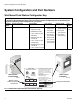
312779E 1:1 2:1 3:1 4:1 5:1 6:1 7:1 8:1 25cc Dose 50cc Dose Ratio 9:1 10:1 11:1 12:1 13:1 14:1 15:1 16:1 17:1 18:1 19:1 20:1 21:1 22:1 23:1 24:1 25:1 26:1 27:1 28:1 29:1 30:1 10cc Dose Fluid: Hydraulic Oil Viscosity: 65.7 centipoise Ratio Tolerance: 5% Valve Setting: 1.25 Turns Open (standard setting) A and B Feed Pressure: 300 psig Test Conditions 0 500 1000 1500 2000 2500 3000 3500 3800 NOTE: Maximum system flow is 3800 cc/min.
1:1 2:1 3:1 4:1 5:1 6:1 7:1 8:1 10cc Dose 25cc Dose 25cc Dose 50cc Dose Ratio 9:1 10:1 11:1 12:1 13:1 14:1 15:1 16:1 17:1 18:1 19:1 20:1 21:1 22:1 23:1 24:1 25:1 26:1 27:1 28:1 29:1 30:1 50cc Dose Fluid: Hydraulic Oil Viscosity: 65.7 centipoise Ratio Tolerance: 5% Valve Setting: 1.25 Turns Open (standard setting) A and B Feed Pressure: 300 psig Test Conditions 0 500 1000 1500 2000 2500 3000 3500 3800 NOTE: Maximum system flow is 3800 cc/min.
Technical Data Technical Data Maximum fluid working pressure . . . . . . . . . . . . . . . Base system: 4000 psi (27.58 MPa, 275.8 bar) Low pressure color change: 300 psi (2.07 MPa, 20.6 bar) Coriolis meter: 2300 psi (15.86 MPa, 158.6 bar) RoboMix system: 190 psi (1.31 MPa, 13.1 bar) Flow control: 190 psi (1.31 MPa, 13.1 bar) Maximum working air pressure . . . . . . . . . . . . . . . . 100 psi (0.7 MPa, 7 bar) Air supply . . . . . . . . . . . . . . . . . . . . . . . . . . . . . . . . . 75 - 100 psi (0.
Graco Standard Warranty Graco warrants all equipment referenced in this document which is manufactured by Graco and bearing its name to be free from defects in material and workmanship on the date of sale to the original purchaser for use. With the exception of any special, extended, or limited warranty published by Graco, Graco will, for a period of twelve months from the date of sale, repair or replace any part of the equipment determined by Graco to be defective.