Repair-Parts ProMix® 2KS 312780F EN Plural Component Proportioner Automatic systems for proportional mixing of plural component coatings, with Wall Mount Fluid Station or RoboMix Fluid Station. For professional use only. For use in explosive atmospheres (except the EasyKey). Important Safety Instructions Read all warnings and instructions in this manual. Save these instructions. See pages 4-7 for model information, including maximum working pressure. Equipment approval labels are on page 3.
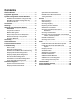
Contents Related Manuals . . . . . . . . . . . . . . . . . . . . . . . . . . . 3 Equipment Approvals . . . . . . . . . . . . . . . . . . . . . . . 3 System Configuration and Part Numbers . . . . . . . 4 Wall Mount Fluid Station Configurator Key . . . . . 4 RoboMix Fluid Station Configurator Key . . . . . . . 6 Standard Features . . . . . . . . . . . . . . . . . . . . . . . 7 Accessories . . . . . . . . . . . . . . . . . . . . . . . . . . . . . . . 8 Warnings . . . . . . . . . . . . . . . . . . . . . . . . .
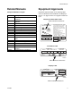
Related Manuals Related Manuals Equipment Approvals Component Manuals in English Equipment approvals appear on the following labels which are attached to the Fluid Station and EasyKey™. See FIG. 1 on page 4 and FIG. 2 on page 6 for label locations.
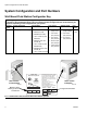
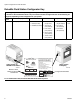
System Configuration and Part Numbers System Configuration and Part Numbers Wall Mount Fluid Station Configurator Key The configured part number for your equipment is printed on the equipment identification labels. See FIG. 1 for location of the identification labels. The part number includes one digit from each of the following six categories, depending on the configuration of your system.
System Configuration and Part Numbers Hazardous Location Approval Models using a G3000, G3000HR, or intrinsically safe Coriolis meter for both A and B meters are approved for installation in a Hazardous Location - Class I, Div I, Group D, T3 or Zone I Group IIA T3. Maximum Working Pressure Maximum working pressure rating is dependent on the fluid component options selected. The pressure rating is based on the rating of the lowest rated fluid component. Refer to the component pressure ratings below.
System Configuration and Part Numbers RoboMix Fluid Station Configurator Key The configured part number for your equipment is printed on the equipment identification labels. See FIG. 2 for location of the identification labels. The part number includes one digit from each of the following six categories, depending on the configuration of your system.
System Configuration and Part Numbers Hazardous Location Approval Models using a G250 or G250HR for both A and B meters are approved for installation in a Hazardous Location Class I, Div I, Group D, T3 or Zone I Group IIA T3. Maximum Working Pressure Maximum working pressure rating for RoboMix Fluid Station Systems is 190 psi (1.31 MPa, 13.1 bar). See the identification label on your EasyKey or RoboMix fluid station for the maximum working pressure. See FIG. 2.
Accessories Accessories Accessory 15V354 Third Purge Valve Kit 15V202 Third Purge Valve Kit 15V536 Solvent Flow Switch Kit 15V213 Power Cable, 100 ft (30.5 m) 15G710 Fiber Optic Cable, 100 ft (30.5 m) 15G614 Flow Control Extension Cable, 40 ft (12.
Warnings Warnings The following warnings are for the setup, use, grounding, maintenance, and repair of this equipment. The exclamation point symbol alerts you to a general warning and the hazard symbols refer to procedure-specific risks. When these symbols appear in the body of this manual, refer back to these Warnings. Product-specific hazard symbols and warnings not covered in this section may appear throughout the body of this manual where applicable.
Warnings WARNING SKIN INJECTION HAZARD High-pressure fluid from gun, hose leaks, or ruptured components will pierce skin. This may look like just a cut, but it is a serious injury that can result in amputation. Get immediate surgical treatment. • Tighten all fluid connections before operating the equipment. • Do not point gun at anyone or at any part of the body. • Do not put your hand over the spray tip. • Do not stop or deflect leaks with your hand, body, glove, or rag.
Important Two-Component Material Information Important Two-Component Material Information Isocyanate Conditions Spraying or dispensing materials containing isocyanates creates potentially harmful mists, vapors, and atomized particulates. Read material manufacturer’s warnings and material MSDS to know specific hazards and precautions related to isocyanates. Prevent inhalation of isocyanate mists, vapors, and atomized particulates by providing sufficient ventilation in the work area.
Grounding Grounding Your system must be grounded. See the Grounding instructions in your ProMix 2KS Installation manual. Pressure Relief Procedure NOTE: The following procedures relieve all fluid and air pressure in the ProMix 2KS system. Use the procedure appropriate for your system configuration. Check Resistance Relieve pressure when you stop spraying, before changing spray tips, and before cleaning, checking, or servicing equipment.
Pressure Relief Procedure Systems with Color Change and without Dump Valves Systems with Color/Catalyst Change and Dump Valves NOTE: This procedure relieves pressure through the sampling valve. NOTE: This procedure relieves pressure through the dump valves. 1. Complete all steps under Single Color Systems, page 12. 1. Complete all steps under Single Color Systems, page 12. 2. Close the A side shutoff valve (SVA), FIG. 4. Open the A side sampling valve (RVA). 2.
Pressure Relief Procedure Color Solenoid Identification Label Catalyst Color Solenoid Identification Label TI12826a Solvent Solenoid Overrides FIG.
Troubleshooting Troubleshooting Table 1: System Alarm Codes Code Description Follow Pressure Relief Procedure, page 12, before cleaning, checking, or servicing equipment. NOTE: Do not use the fluid in the line that was dispensed off ratio as it may not cure properly. Alarm Codes Table 1 lists the system alarm codes. See the system operation manual for complete information on alarm troubleshooting.
Troubleshooting Solenoid Troubleshooting RoboMix Fluid Station Dose Valve B Override Button Dose Valve A Override Button TI12655a Wall Mount Fluid Station F2 F1 J1 Power Fiber Optic CAN J13 CAN J12 1 J14 1 J15 GFB 2 GFB 1 Dump B J9 Dump A 1 Purge B Dose A Dose B Purge A Valve 3rd Purge J3 1 J8 Dump Valve A Dump Valve B GFB 1 Optional Solenoid Locations GFB 2 3rd Purge Valve Solenoid Dose Valve A Solenoid Dose Valve B Solenoid Purge Valve A Solenoid Purge Valve B Solenoid TI1
Troubleshooting NOTE: Refer to the Schematic Diagrams, page 30. If the dispense or purge valves are not turning on or off correctly, it could be caused by one of the following. Cause 1. Air regulator pressure set too high or too low. Solution Check air pressure. 80-90 psi (550-630 kPa, 5.5-6.3 bar) is commonly used. Do not go below 70 psi (490 kPa, 4.9 bar) or above 120 psi (0.8 MPa, 8 bar). 2.
Troubleshooting Wall Mount Fluid Manifold Troubleshooting See FIG. 6. To remove the fluid manifold, see page 49. See manual 312781 for complete information on the fluid manifold.
Troubleshooting EasyKey Barrier Board Diagnostics See FIG. 7 and Table 2 to troubleshoot the EasyKey barrier board. Also see the EasyKey Electrical Schematic on page 31 and the System Electrical Schematic on pages 32 and 33. J4, Pin 1 J1, Pin 1 D5 F1 F2 F4 F3 D4 J5, Pin 1 FIG. 7: 255786 EasyKey Barrier Board Table 2: EasyKey Barrier Board Diagnostics Connector Description Diagnosis J1 AC Power Input n/a J4 24 Vdc Power Input to EasyKey Display Board D5 turns on.
Troubleshooting EasyKey Display Board Diagnostics See FIG. 8 and Table 3 to troubleshoot the EasyKey display board. Also see the EasyKey Electrical Schematic on page 31 and the System Electrical Schematic on pages 32 and 33.
Troubleshooting Table 3: EasyKey Display Board Diagnostics Connector/ Indicator Description Connector/ Indicator Description J1 Graphic Display Backlight J9 24 Vdc Power Input/Alarm Output J4 Ribbon Cable to Membrane J10 RS485 Communication Terminals J5 Inputs and Outputs D7 (green) J6 Remote I/O LED turns on when power is supplied to board J7 Fiber Optic Cable Input (black) J8 Fiber Optic Cable Output (blue) 312780F D11 (yellow) LED blinks (heartbeat) when board is operating P1 Eth
Troubleshooting Discrete I/O Board Diagnostics See FIG. 9 and FIG. 10 to troubleshoot the Discrete I/O board. Also see the System Electrical Schematic on pages 32 and 33.
Digital Output Common/Power Special Output #1 Special Output #2 Special Output #3 Digital Output Common/Power Special Output #4 Troubleshooting JLS Digital Output Common/Power Flow Rate Alarm Output Flow Calibrate Active Fill Active Mix Ready Output LED D1 (green) Mix Active Output Purge/Recipe Change Active Output Digital Output Common/Power Recipe Change Input Recipe Bit 5 Input Recipe Bit 4 Input Recipe Bit 3 Input Recipe Bit 2 Input Recipe Bit 1 Input Recipe Bit 0 Input Digital Input Common
Troubleshooting 24 312780F
Troubleshooting Fluid Station Control Board Diagnostics See FIG. 11 and Table 4 to troubleshoot the fluid station control board. Also see the System Electrical Schematic on pages 32 and 33. D18 D19 J4 (Fiber Optic Output - blue) F1 (Fuse) F2 (Fuse) J6 (Fiber Optic Input - black) D15 J10 (Power Input) D45 D16 J11 (Color Change Module) D46 D17 Set Switch S1 as shown below. J7 (Not Used) D44 TI15223a D20 Set switch S1 to OFF (up) if system has Booth Control AND Color Change.
Troubleshooting Pin 1 AFS #1 J1 J10 AFS #2 Solvent Switch GFB 1 PS J4 J6 GFB 2 PS J11 J13 (Not Used) Pin 1 J12 Solvent Meter Spare Pin 1 Flow Meter A J3 Flow Meter B Pin 1 Dose Valve A Dose Valve B J9 Spare + G s + G s J7 + G s + G s + + + J14 J15 Pin 7 (plugged) + Dump Valve B + GFB 1 Pin 1 + GFB 2 + Dump Valve A + Spare + Pin 1 + 3rd Flush Valve + Purge Valve B (Solvent) Spare Pin 1 (plugged) + Purge Valve A (Air) Pin 7 (plugged) J8 FIG.
Troubleshooting Table 4: Fluid Station Control Board Diagnostics LED Connector and Pin Nos. Signal Description Diagnosis D15 J1, 1 & 2 Air Flow Switch 1 Turns on when gun 1 is triggered. D16 J1, 5 & 6 Solvent Flow Switch Turns on when solvent is flowing. D17 J1, 9 & 10 Gun Flush Box 2 Pressure Switch Turns on when a gun is in Gun Flush Box 2. D18 J10 Power Turns on when power is supplied to the board. D19 n/a Communication (yellow) Turns on when board is communicating with EasyKey.
Troubleshooting Color Change Board Diagnostics See FIG. 13 and Table 5 to troubleshoot the color change board. Also see the System Electrical Schematic on pages 32 and 33. To replace the color change board, see manual 312787. J8, Pin 1 D33 D34 D43 D31 D44 D29 J9, Pin 1 J15, Pin 1 D39 D41 D32 D35 D38 J16, Pin 1 D27 D37 J14, Pin 1 D45 D30 D46 D28 J10, Pin 1 D36 D9 D10 D8 F1 (Fuse) J7 J11 FIG.
Troubleshooting Table 5: Color Change Board Diagnostics LED Connector and Pin Nos. Board 1 Signal Description Board 2 Signal Description Diagnosis D8 n/a Board OK Board OK Blinks (heartbeat) during normal operation. D9 n/a Communication (yellow) Communication (yellow) Turns on when board is communicating with ProMix 2KS. D10 J7 Power Power Turns on when power is supplied to the board.
Schematic Diagrams Schematic Diagrams System Pneumatic Schematic COLOR CHANGE CONTROL A B SE BE CLO 2 TU 5/3 N E OP DOSE A VALVE 12 VDC 4-WAY SOLENOID A B SE BE CLO 2 TU 5/3 N E OP DOSE B VALVE 12 VDC 05 AIR INPUT 4-WAY SOLENOID CONTROL AIR 3/8 AIR FILTER MANUAL DRAIN 5 MICRON WALL MOUNT ONLY A B 4-WAY SOLENOID A B 12 VDC A B AIR EXHAUST MUFFLER PURGE AIR SE BE CLO 2 TU 5/3 N E OP PURGE A VALVE SE BE CLO 2 TU 5/3 EN OP PURGE B VALVE SE BE CLO 2 TU 5/3 N E OP PURGE C VALVE (OPTIONAL)
2780F DISPLAY BOARD P1 BARRIER BOARD J9 1 2 3 4 RJ45 DISPLAY BOARD RJ45 J5 J1 J4 24 VDC+ IN RED 18 AWG BLACK 18 AWG RED/BLACK/WHITE 22 AWG J5-1 J5-2 J5-3 SHIELD/GRND COMMON (BLACK) +12 VDC I/S (WHITE) UNUSED UNUSED J1-1 UNUSED J1-2 UNUSED J1-4 J1-3 UNUSED RED 18 AWG BLACK 18 AWG J1-5 J4-1 J4-2 J4-3 GREEN/BLACK/WHITE 22 AWG IS POWER 12 VDC + + + + - RED 18 AWG BLACK 18 AWG DC OK + - - 24 VDC+ HIGH VOLTAGE IN POWER SUPPLY 24 VDC+ OUTPUT GND LUG COMMON R
Schematic Diagrams System Electrical Schematic NOTE: The electrical schematic illustrates all possible wiring expansions in a ProMix 2KS system. Some components shown are not included with all systems.
Schematic Diagrams System Electrical Schematic NOTE: The electrical schematic illustrates all possible wiring expansions in a ProMix 2KS system. Some components shown are not included with all systems.
Schematic Diagrams RoboMix Panel Board Schematic J10 +12VDC I/S COM SHIELD TO EASYKEY J5 1 2 3 1 2 3 4 5 6 J7 TO COLOR CHANGE GRD (BLK) +12VDC (RED) SHIELD (BARE) CAN H (WHT) CAN L (BLU) MANIFOLD NOT USED DOSE B DOSE A 3 2 5 4 1 MH2 J1 6 5 4 3 2 1 1 2 3 4 5 6 7 8 9 10 6 5 4 3 2 1 1 2 3 4 5 6 6 5 4 3 2 1 J12 1 2 3 4 5 6 J9 BLACK RED BLACK RED BLACK RED PURGE A NOT USED BLACK RED BLACK RED BLACK RED J15 DUMP A NOT USED NOT USED BLACK RED BLACK RED BLACK RED NOT USED NOT USED NOT USED NOT
Schematic Diagrams 312780F 35
Schematic Diagrams Tubing Schematic B3 13 B1 13 14 A2 A6 B7 B5 DB AT A4 DA A8 TI13857a B1 B3 B5 TI13858a B7 14 TI13856a TI13859a A2 36 A4 A6 A8 DA DB 312780F
Schematic Diagrams Table 6: Tubing Chart Color Description Starting Point Ending Point Tube OD in. (mm) Tube Ref. No.
Service Service Before Servicing 3. Shut off ProMix 2KS power (0 position). FIG. 14. 4. If servicing EasyKey, also shut off power at main circuit breaker. • • • • • To avoid electric shock, turn off EasyKey power before servicing. Servicing EasyKey display exposes you to high voltage. Shut off power at main circuit breaker before opening enclosure. All electrical wiring must be done by a qualified electrician and comply with all local codes and regulations.
Service Servicing EasyKey 5. Disconnect graphic display power cable (J1) from the display board (210c). Updating Software 6. Separate graphic display (210b) from display board (210c) [connector J2 on back of board]. To update software, upload new software from your PC using the basic web interface. See manual 313386. NOTE: If using the Graco Gateway in your system, disconnect its cable from the EasyKey before updating the ProMix 2KS software. 7.
Service Replacing Line Filter Replacing Power Switch 1. Follow Before Servicing, page 38. 1. Follow Before Servicing, page 38. 2. Unlock and open EasyKey door with its key. 2. Unlock and open EasyKey door with its key. 3. Note position of line filter input and output wires. See EasyKey Electrical Schematic, page 31. Disconnect wires and remove line filter (214l) from bracket (214m). See FIG. 16. 3. Note position of power switch wires. See EasyKey Electrical Schematic, page 31.
Service 312780F 41
Service Replacing Barrier Board 8. Install the cover (214b) with 2 screws (214k), using the security tool. 9. Connect cables to J1, J4, and J5. 10. Close and lock EasyKey door with key. 11. Turn on power at main circuit breaker. NOTICE To avoid damaging circuit board when servicing, wear Part No. 112190 grounding strap on wrist and ground appropriately. 12. Turn EasyKey power on to test operation. Replacing Barrier Board Fuses 1. Follow Before Servicing, page 38. 2.
Service J4 (Power to Display Board) J1 (Power In) 214g 214g F2 F1 F4 F3 214h J5 (Power to Fluid Station) 214g Do not remove this screw 214h Front of Barrier Board, showing Fuses and Connectors 1 1 Z Apply thermal compound to surface of heatsink (Z). Back of Barrier Board, showing Heatsink (Z) FIG.
Service Replacing Air Filter Element Wall Mount Fluid Station Preparation Removing a pressurized air filter bowl could cause serious injury. Depressurize air line before servicing. Check the 5 micron air manifold filter daily and replace element (317a, Part No. 114228) as needed. 1. Close main air shutoff valve on air supply line and on unit. Depressurize air line. 1. Follow Before Servicing, page 38. 2. Loosen the 4 screws (307), then remove the Wall Mount Fluid Station cover (322). FIG. 20. 2.
Service 314 343 306 320 319 305 316 322 314 307 302 315 301 303 See Detail Below 340 341 318, 332 339 325 TI12425a 321 335 317 Solenoid Manifold Detail 309 311 308 323 342 328 330 328 313 324 331 312 TI12426a FIG.
Service Replacing Control Board 3. Remove 4 screws (303). Remove connector jam nuts on the outside of the enclosure (301). Remove control board (302). FIG. 20. 4. Install new control board (302) with 4 screws (303). NOTICE To avoid damaging circuit board when servicing, wear Part No. 112190 grounding strap on wrist and ground appropriately. 5. Connect cables to control board (302). FIG. 21.
Service Replacing Solenoids The Wall Mount Fluid Station has a minimum of 4 solenoids. If you have options installed, you have additional (optional) solenoids for each. See Table 7 and Schematic Diagrams, page 30. To replace a single solenoid: Table 7: Wall Panel Solenoids Solenoid Actuates Fuse 1 Dose Valve A F1 2 Dose Valve B F1 3 Air Purge Valve F1 4 Solvent Purge Valve F1 Standard Optional 5 Third Flush Valve F2 1.
Service Servicing Flow Meters Mounted on Wall Panel 2. Secure meter (M) and plate (MP) to fluid station with screws (MS). NOTE: You must assemble the meter sensor to the meter body before connecting the cable to the sensor for the meter to function properly. 3. Connect meter cable (CC). See FIG. 23. Coriolis Meter 4. Connect fluid line (P). 1. Follow Before Servicing, page 38. 5. Calibrate meter as instructed in ProMix Operation manual. 2. To remove and service the Coriolis meter, see manual 313599.
Service Servicing Fluid Manifold Removal 1. Follow Servicing Flow Meters Mounted on Wall Panel, Removal steps 1-5, page 48. 341 2. Disconnect air and fluid lines from the manifold (4). 3. Holding onto the fluid manifold (4), loosen the three screws (341) holding the bracket (325) to the fluid station. Lift the fluid manifold (4) and pull it away from the panel. Service as instructed in the Fluid Mix Manifold manual 312781. Installation 325 1.
Service RoboMix Fluid Station Preparation 2. Remove the RoboMix cover (410). FIG. 26. 3. Note the position of all RoboMix hoses, then disconnect them. 1. Follow Before Servicing, page 38. 410 B Inlet Air Logic Inlet A Inlet Air Purge Inlet Solvent Inlet B Dump Outlet A Dump Outlet TI12512a FIG.
Service Replacing Control Board 4. Remove 4 screws (428). Remove control board (426). FIG. 28. 1. Follow Preparation, page 50. 2. Remove the control board cover (427). FIG. 27. 426 428 427 427 TI12579a FIG. 27: Remove Control Board Cover 3. Disconnect fiber optic wires (J4, J6) and all cables (J1, J3, J5, J7, J8, J9, J12, J13, J14, J15) from control board (426). FIG. 29. TI12648a FIG. 28: Remove Control Board 5. Install new control board (426) with 4 screws (428). 6.
Service Replacing Control Board Fuse 1. Follow Preparation, page 44. 2. Locate fuse F1 on the control board. See FIG. 29. Remove the screw and metal strap. Replacing the fuse with a non-Graco fuse voids the IS system safety approval. 3. Pull the fuse away from the board. 4. Install the new fuse (497). 5. Reinstall covers (427, 410). Fuse Part No. Description F1 123690 Fuse; 125 mA, intrinsically safe J4 (F.O. Output - F1 (497) J6 (F.O.
Service Replacing Solenoids The RoboMix Fluid Station has a minimum of 4 solenoids. If you have optional 3rd flush valve or dump valve kits installed, you have additional (optional) solenoids for each additional valve. Refer to Table 8 and Schematic Diagrams, page 30. 4. Unscrew 2 screws (P) and remove solenoid (486). See FIG. 31 and Table 8. 486 To replace a single solenoid: 1. Follow Preparation, page 50. Shut off power at the main circuit breaker. 7 6 5 4 3 2 1 P 2.
Service G250 and G250HR Flow Meters 5. Calibrate meter as instructed in ProMix Operation manual. Removal 6. Place board into its correct position and reassemble RoboMix Panel. 1. Follow Preparation, page 50. 2. Unscrew cable from meter connector (CC). FIG. 32. M 3. Unscrew M6 screws (442) and washers (440) from bottom of meter mounting plate (438) with socket wrench. FIG. 32. CC P H 4. Disconnect the fluid line from the meter inlet (P). 412 5.
Service Servicing RoboMix Manifold Manifold Service Kit 15V480 is available. Kit parts are marked with an asterisk, for example (502*). For best results, use all parts in the kit. Lubricate all o-rings during assembly. 2. Disconnect all fluid and air lines from the RoboMix manifold (477). 3. Unscrew the flexible mixer (474) from the integrator cap (511). 4. Remove the screws (403, 478) and the spacer (465, on the B side). Remove the manifold assembly (477) from the RoboMix fluid station. FIG. 34. 1.
Service 5. Unscrew the integrator cap (511) and housing (510). Inspect the mixer (508) and mix cap (509). Replace the o-rings (504*). FIG. 35. 6. Unscrew the integrator manifold plug (507). Remove the integrator base (503). Replace both o-rings (502*, 504*). NOTICE Keep A side and B side parts separate when disassembling, to prevent contamination during reassembly. 7. Unscrew the A and B dose valves (521) from the valve adapters (517). Replace the o-rings (518*).
Service Servicing Flow Control 6. Install a new o-ring (602) on the pressure sensor (620) and screw the sensor into the fluid plate (606). Preparation 7. Reinstall the fluid plate on the air plate. Be careful not to pinch the pressure sensor cable. Torque the screws (605) to 30-40 in-lb (3.4-4.5 N•m). 8. Reconnect the three cables to J1, J2, and J4 on the circuit board (618). FIG. 36. 1. Follow Before Servicing, page 38. 2. Disconnect all air and fluid lines from the flow control regulator. 3.
Service Servicing the V/P Valve 615 1. Follow Before Servicing, page 38. 2. Remove the four screws (605) holding the bracket (614) to the housing (611). FIG. 37. 3. Carefully separate the bracket from the housing and disconnect the V/P valve cable from J2 on the circuit board (618). FIG. 36. *613 604* *610 Flow direction 606 4. Remove the two screws (619a) and o-rings (619b). Install the new valve (619) with new screws and o-rings. *609 602*‡ *612 620*‡ *617 *623 *616 5.
Parts Parts ProMix 2KS Automatic Wall Panel System Configurator Key The configured part number for your equipment is printed on the equipment identification labels. See the illustrations below for location of the identification labels. The part number includes one digit from each of the following six categories, depending on the configuration of your system. The digits in this table do not correspond to ref. nos. in the parts lists or parts drawings.
Parts Part No. AD000N to AD742Y, includes EasyKey with LCD display 2 10 2 310 11 16 12 329 15 2 14 3 8 4 2 9 Items 310 and 329 are part of the Wall Mount Fluid Station. See the parts list beginning on page 69 for descriptions.
Parts Part No. AD000N to AD742Y, includes EasyKey with LCD display Ref. No. Configured Digit (see page 59) or part usage Part No.
Parts 62 312780F
Parts ProMix 2KS Automatic RoboMix Panel System Configurator Key The configured part number for your equipment is printed on the equipment identification labels. See the illustrations below for location of the identification labels. The part number includes one digit from each of the following six categories, depending on the configuration of your system. The digits in this table do not correspond to ref. nos. in the parts lists or parts drawings.
Parts Part No. RD000N to RD242Y, includes EasyKey with LCD display 2 10 11 484 12 23 2 25 2 24 483 27 2 474 16 25 1 27 3 15 1 Meters (8 and 9) are underneath the RoboMix cover. See page 72 for location. 2 Items 474, 483, and 484 are part of the RoboMix Fluid Station. See the parts list beginning on page 70 for descriptions.
Parts Part No. RD000N to RD242Y, includes EasyKey with LCD display Ref. No. Configured Digit (see page 59) or part usage Part No.
Parts EasyKey Controls 277869 EasyKey, with Display 206 Detail of Display Interface Kit (210) 214f 214c 208 201 210a 210d 202 214h 214l, 214m 210b 210c (not part of kit) 210e 214g TI12554a 214a 211 221 214b TI12417b 214k 201 214d 214f 212 203 218 214l, 214m 209 214e, 214j 207 205, 206, 209 213, 223, 206 66 204 215 221 211 TI12496b 312780F
Parts 277869 EasyKey, with Display Ref. No. Part No.
Parts Wall Mount Fluid Station 314 320 306 319 305 316 322 314 307 302 315 301 303 See Detail Below 340 339 341 325 318, 332 321 335 Control Board Fuses TI12425a 343 317 Solenoid Manifold Detail 309 311 308 323 342 328 330 328 313 324 331 312 TI12426a 68 TI12652b 312780F
Parts Wall Mount Fluid Station NOTE: Parts are shown on page 68, unless noted. Ref. No. 301 302 303 304 305 306 307 308 309 310 311 312 313 314 315 316 317 317a 318 319 320 321 322 323 324 Part No. Description 256529 ENCLOSURE 255765 BOARD, circuit n/a SCREW, machine, pan hd; 4-40 x 3/16 in. (5 mm) 119257 CONNECTOR, bar, ground 119162 CONNECTOR, plug, 6-position 116773 CONNECTOR, plug,10-position 113783 SCREW, machine, pan hd; 1/4-20 x 1/2 in.
Parts RoboMix Fluid Station NOTE: Parts are shown on pages 72 and 73, unless noted. RoboMix Panel, no dump valve RoboMix Panel, one dump valve RoboMix Panel, two dump valves* Ref. No. 401 402 403 404 406 407 408 409 410 411 412 413 414 415 70 Part No. Description 15U712 PANEL, RoboMix C19979 SCREW, cap, socket-hd; 10-24 x 3/8 in. (10 mm) Panel with no dump valve Panel with one dump valve Panel with two dump valves C19798 SCREW, cap, socket-hd; 1/4-20 x 3/8 in.
Parts Ref. No. 428 429 431 432 433 434 435 436 437 438 439 440 441 442 443 458 463 464 465 466 474 477 Part No. Description 107295 SCREW, machine, pan-hd; 4-40 x 3/16 in. (5 mm) 15U725 MANIFOLD, solenoid, RoboMix 109193 ELBOW, tube; 10-32 x 5/32 in. (4 mm) OD tube 108382 FITTING, seal, o-ring; 10-32 120053 ELBOW, tube; 10-32 x 1/4 in. (6 mm) OD tube 111328 CONNECTOR, male; 10-32 x 5/32 in.
Parts RoboMix Fluid Station RoboMix Panel, two dump valves shown Detail of Circuit Board Assembly 426 428 428 497 410 464 420 463 425 427 412 436 419 420 TI12508a 420 Detail of Flow Meter Assembly 1 See page 65 for description. 412 9 404 1 439 419 1 434 8 429 433 404 403 438 TI12507a 432 437 401 See page 73 for detail.
Parts RoboMix Fluid Station Detail of Ratio Check Kit (493) Detail of Connection Ports A Inlet Air Logic Inlet B Inlet 402 490; Air Purge Inlet 423; A Dump Outlet 423; B Dump Outlet 458; Solvent Inlet TI12514a 477 See page 74 for detail.
Parts 256654 RoboMix Manifold Ref. No. Part No.
Parts 256654 RoboMix Manifold 521 *518 520 511◆ 504◆* 517 506 510◆ 514 505* 504◆* 509◆ *◆502 508◆ 503 515* 516 *◆504 522* 515* 507 505* 512 501 528 513 519* 529 312780F TI12513a 75
Parts 249849 Flow Control Regulator Ref. No. Part No. Description 601* 102980 602‡* n/a NUT, full, hex; 4-40 O-RING; chemically resistant fluoroelastomer 603 112698 ELBOW; 1/8 npt(m) x 1/4 in. (6 mm) OD tube 604* n/a O-RING; chemically resistant fluoroelastomer 605 n/a SCREW, cap, socket-hd; 10-32 x 1/2 in.
Parts Color Change Accessory Kits Low Pressure Color Change Kits Kit Part No.
Parts 78 312780F
Technical Data Technical Data Maximum fluid working pressure . . . . . . . . . . . . . . . Base system: 4000 psi (27.58 MPa, 275.8 bar) Low pressure color change: 300 psi (2.07 MPa, 20.6 bar) Coriolis meter: 2300 psi (15.86 MPa, 158.6 bar) RoboMix system: 190 psi (1.31 MPa, 13.1 bar) Flow control: 190 psi (1.31 MPa, 13.1 bar) Maximum working air pressure . . . . . . . . . . . . . . . . 100 psi (0.7 MPa, 7 bar) Air supply . . . . . . . . . . . . . . . . . . . . . . . . . . . . . . . . . 75 - 100 psi (0.
Graco Standard Warranty Graco warrants all equipment referenced in this document which is manufactured by Graco and bearing its name to be free from defects in material and workmanship on the date of sale to the original purchaser for use. With the exception of any special, extended, or limited warranty published by Graco, Graco will, for a period of twelve months from the date of sale, repair or replace any part of the equipment determined by Graco to be defective.