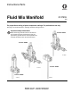
Instructions-Parts Fluid Mix Manifold 312781E EN For proportional mixing of plural component coatings. For professional use only. See page 2 for model information, including maximum working pressure. Important Safety Instructions Part No. 256875 Read all warnings and instructions in this manual. For complete warnings and instructions see your proportioning system manual. Hazard symbols refer to specific procedure risks. Save all instructions. Part No. 289695 TI14362a Part No.
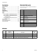
Related Manuals Contents Related Manuals Related Manuals . . . . . . . . . . . . . . . . . . . . . . . . . . . 2 Models . . . . . . . . . . . . . . . . . . . . . . . . . . . . . . . . . . . 2 Installation . . . . . . . . . . . . . . . . . . . . . . . . . . . . . . . . 3 Operation . . . . . . . . . . . . . . . . . . . . . . . . . . . . . . . . . 7 Maintenance . . . . . . . . . . . . . . . . . . . . . . . . . . . . . . . 8 Troubleshooting . . . . . . . . . . . . . . . . . . . . . . . . . . . . 9 Repair . .
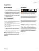
Installation Installation Air Connections Grounding See FIG. 1, FIG. 2, or FIG. 3. 1. Connect 5/32 in. (4 mm) OD air tubes from the valve solenoids to the air inlets of each valve. 2. ProMix 2KS and ProMix 3KS systems only: Connect an air supply line to air purge valve (APV) inlet (1/4 in. ID tube is supplied, with tag). 3. Pressurize the system with air, and check for leaks, then relieve air pressure. Fluid Connections See FIG. 1, FIG. 2, or FIG. 3. 1.
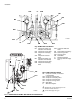
Installation FI DVA DVB MB MS MA RVB RVA TI12556a APV AT SVA SM SVB SPV Key: ProMix 2KS Fluid Station MA DVA RVA SVA FI MB DVC DVB RVB MC Component A Meter (not included in mix manifold) Component A Dose Valve Component A Sampling Valve Component A Shutoff Valve Component B Meter (not included in mix manifold) Component B Dose Valve Component B Sampling Valve SVB Component B Shutoff Valve MS Solvent Meter (accessory) SPV Solvent Purge Valve APV Air Purge Valve SM Static Mixer FI 2KS Fluid
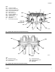
Installation Key: MA Component A Meter DVA1 Component A Dose Valve DVA2 Second Color/Catalyst Valve DVA3 Third Color/Catalyst Valve SVA Solvent Valve A CVA Meter A Check Valve MB Component B Meter DVB Component B Dose Valve SVB Solvent Valve B CVB Meter B Check Valve SM Static Mixer FI Fluid Integrator Assembly FI SVA SVB DVA1 DVB DVA2 and DVA3 (behind) CVB CVA MA MB ti15699a SM FIG. 2.
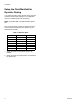
Installation Setup the Fluid Manifold for Dynamic Dosing If you will be operating using dynamic dosing, the fluid manifold must be setup properly for your application. Order the 15U955 Injection Kit (accessory). NOTE: For ProMix 3KS, order two 15U955 Injection Kits. See your proportioner manuals for setup instructions, and to select the appropriate size restrictor for your selected flow and ratio. Table 1: Restrictor Sizes * Size Code Orifice Size Part No. 2* 3* 4* 5✓ 6✓ 7* 8✓ .020 .030 .040 .050 .
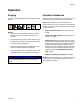
Operation Operation Purging Operation Guidelines Follow the purging procedure in the proportioner system manual. Manifold operation is dependent on the system it is connected to. Follow the system operation instructions. NOTE: After the system has been shut down for a period of time, it is normal for component solenoids and valves to cycle rapidly until system pressure is built back up when restarted.
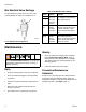
Maintenance Mix Manifold Valve Settings Table 2: Mix Manifold Valve Settings To open dispense or purge valves, turn hex nut (E) counterclockwise. To close, turn clockwise. FIG. 4. Valve Setting Function Dose Hex nut (E) 1-1/4 turns out from fully closed Limits maximum fluid flow rate into integrator and minimizes valve response time. Shutoff Fully open during Run/Mix operation Closes component ports to integrator during ratio check or meter calibration. Open ports during Run/Mix operation.
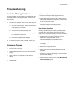
Troubleshooting Troubleshooting Isolate a Mixing Problem A mixing problem can be caused by a problem with the controller, meters, and solenoid valves, as well as the mix manifold. 1. To isolate the problem, check for any visible faults or errors: a. Are all air and fluid tubes, hoses, and electrical cables properly connected? b. Are valves and controls properly set? c. Do the fluid supplies, solenoids, and spray gun have sufficient air pressure? Unbalanced Pressure 1.
Repair Repair To reduce the risk of injury, including fluid injection, follow the Pressure Relief Procedure in your proportioning equipment manual before cleaning, checking, or repairing equipment. NOTE: Purge the mix manifold with solvent after repair to remove any excess grease that is used for lubricating parts. Remove the Integrator Mixer See the Parts drawings on pages 14-19. Clean and inspect all parts. Apply pipe sealant to all pipe threads when reassembling.
Repair Repair the Valves and Seats (ProMix 2KS and ProMix 3KS only) Valve Seat Kit 24A861 is available. See page 15. Parts included in the kit are marked with a symbol, for example (16‡). For best results, use all parts included in the kit. See the Parts drawings on pages 14 and 16. Clean and inspect all parts. Apply pipe sealant to all pipe threads when reassembling. 5. Remove the screws (20). Lift the adapter (17) and valve (19) off the shutoff valve manifold (11 or 36). 6.
Repair Rebuild the Mix Manifold Manifold Rebuild Kit 15U931 is available. See page 15. Parts included in the kit are marked with a symbol, for example (3*). For best results, use all parts included in the kit. See the Parts drawings on pages 14-19. Clean and inspect all parts. Apply pipe sealant to all pipe threads when reassembling. 1. Relieve pressure. 2. ProMix 2KS and ProMix 3KS only: Follow steps 2-6 under Repair the Valves and Seats (ProMix 2KS and ProMix 3KS only), page 11.
Repair 312781E 13
Parts Parts Part No. 289695, for ProMix 2KS Proportioner 1 21 Apply pipe sealant to all pipe threads when reassembling.
Parts Part No. 289695, for ProMix 2KS Proportioner Ref. No. 1 3 5* 11 12 13* 14* 15*‡ 16‡ 17 18* 19 Part No.
Parts Part No. 256875, for ProMix 3KS Proportioner 1 21 Apply pipe sealant to all pipe threads when reassembling.
Parts Part No. 256875, for ProMix 3KS Proportioner Ref. No. 1 3 5* 8 9 Part No.
Parts Part No.
Parts Part No. 262399, for ProMix 2KE Proportioner, Dynamic Dosing 23 55 3 31* 35 58 40* 57 36 37 39* 45 59 *5 56 38 31* *39 1 54 29 25 30 28 Ref. 1 3 5* 23 24 25 28 29 30 31* 35 36 37 38 39* 40* 45 54 55 56 57 58 59 * Part ----15T592 ----15B588 15D430 118822 118830 118831 101885 ----15T943 ----15T748 15T749 --------16D658 15U955 ----16D019 105510 100609 112223 Description Qty.
Parts 20 312781E
Technical Data Technical Data Maximum Fluid Working Pressure . . . . . . . . . . . . . . . . . . 289695, 256875, and 262398: 4000 psi (28 MPa, 280 bar) 262399: 4500 psi (31 MPa, 310 bar) Dispense Valve Fluid Inlet Size . . . . . . . . . . . . . . . . . . . . 1/4 npt(f) Dispense Valve Air Inlet Fitting Size . . . . . . . . . . . . . . . . . 5/32 in. (4 mm) OD tube Wetted Parts. . . . . . . . . . . . . . . . . . . . . . . . . . . . . . . . . . .
Graco Standard Warranty Graco warrants all equipment referenced in this document which is manufactured by Graco and bearing its name to be free from defects in material and workmanship on the date of sale to the original purchaser for use. With the exception of any special, extended, or limited warranty published by Graco, Graco will, for a period of twelve months from the date of sale, repair or replace any part of the equipment determined by Graco to be defective.