Instructions-Parts Color and Catalyst Change Valve Stacks 312783E EN For color/catalyst changing or distribution of industrial paints and coatings or fluids. Important Safety Instructions Read all warnings and instructions in this manual. For complete warnings and instructions see your proportioning system manual. Hazard symbols refer to specific procedure risks. Save all instructions. See pages 3 and 4 for model information, including maximum working pressure.
Related Manuals Contents Related Manuals . . . . . . . . . . . . . . . . . . . . . . . . . . . 2 Models . . . . . . . . . . . . . . . . . . . . . . . . . . . . . . . . . . . 3 Low Pressure Valve Stacks . . . . . . . . . . . . . . . . 3 High Pressure Valve Stacks . . . . . . . . . . . . . . . . 4 Installation . . . . . . . . . . . . . . . . . . . . . . . . . . . . . . . . 5 Parts . . . . . . . . . . . . . . . . . . . . . . . . . . . . . . . . . . . . . 6 Low Pressure Color/Catalyst Valve Stacks . . . . .
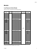
Models Models Low Pressure Valve Stacks 300 psi (2.1 MPa, 21 bar) Maximum Fluid Working Pressure Valve Stack Part No. Series Valve Stack Description Valve Part No.
Models High Pressure Valve Stacks 3000 psi (21 MPa, 210 bar) Maximum Fluid Working Pressure Valve Stack Part No. Series Valve Stack Description Valve Part No.
Installation Installation A 1. Connect 5/32 in. (4 mm) OD air actuation tubes from the valve solenoids to the air inlets (A) of each valve. See FIG. 1. S NOTE: The high pressure color change valve uses a spring-operated valve closure vent (20) which does not require a second air actuation line. If you are installing a bare valve, remove the elbow fitting from the top port and install the breather vent. Replace the spring with the one marked with black stain.
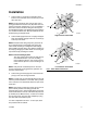
Parts Parts Low Pressure Color/Catalyst Valve Stacks 16 10 8 9 3 7 4 2 *15 11 8 1 12 2 Ref. No. 1 2 3 4 6 7 8 9 10 11 12 15* 16 Part No. Description 15X304 VALVE, low pressure; includes item 15; see manual 312782 --SCREW; 5/16-24 x 5/8 in.
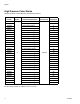
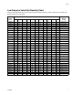
Parts Low Pressure Valve Part Quantity Chart Find your Valve Stack Part No. in the left column and the desired reference number in the top row to find the part quantity used in your valve stack. Valve Stack Part No. Reference Numbers 1 2 3 4 7 8 9 11 12 15 16 Weight lb (kg) 256994 2 4 2 2 2 2 1 0 0 2 4 2.35 (1.07) 15V812 3 8 3 3 3 3 2 1 1 3 6 4.05 (1.84) 256290 4 8 4 4 4 3 2 0 0 4 6 4.70 (2.13) 15V813 5 12 5 5 5 4 3 1 1 5 8 6.40 (2.
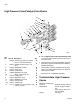
Parts High Pressure Color/Catalyst Valve Stacks 16 10 8 9 ‡7 ‡5 3 ‡5 4 2 1 *‡15 8 11 8 6 ti11666c 2 Ref. No. 1 Part No. Description 15X303 VALVE, high pressure; includes item 15; see manual 312782 2 15T875 SCREW; 5/16-24 x 5/8 in.
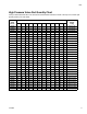
Parts High Pressure Valve Part Quantity Chart Find your Valve Stack Part No. in the left column and the desired reference number in the top row to find the part quantity used in your valve stack. Valve Stack Part No. Reference Numbers 1 2 3 4 5 7 8 9 11 15 16 20 Weight lb (kg) 256995 2 4 2 2 4 2 2 1 0 2 4 2 2.60 (1.18) 15V816 3 8 3 3 6 3 4 2 1 3 6 3 5.05 (2.29) 256339 4 8 4 4 8 4 3 2 0 4 6 4 5.20 (2.36) 15V817 5 12 5 5 10 5 5 3 1 5 8 5 7.
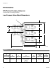
Dimensions Dimensions NOTE: Mounting bracket 15U927 is available to mount the color valve stack to a ProMix 2KS Fluid Station. See manual 312787 for mounting instructions. Low Pressure Valve Stack Dimensions G A B F B D B C E TI13553a FIG. 2. Low Pressure Valve Stack Dimensions A (manifold cap and screws) B (manifold) C (fluid port) D (A+total of B+C) E (width) F (mounting hole dimension) 0.5 in. (13 mm) 2.061 in. (52.3 mm) 1.07 in. (27.2 mm) Example shown with three manifolds: 7.75 in.
Dimensions High Pressure Valve Stack Dimensions G A B F B D B C E TI13554a FIG. 3. High Pressure Valve Stack Dimensions A (manifold cap and screws) B (manifold) C (fluid port) D (A+total of B+C) E (width) F (mounting hole dimension) 0.62 in. (15.7 mm) 2.25 in. (57.2 mm) 1.07 in. (27.2 mm) Example shown with three manifolds: 8.44 in. (214 mm) 10.16 in. (258.1 mm) 2.25 in. (57.
Graco Standard Warranty Graco warrants all equipment referenced in this document which is manufactured by Graco and bearing its name to be free from defects in material and workmanship on the date of sale to the original purchaser for use. With the exception of any special, extended, or limited warranty published by Graco, Graco will, for a period of twelve months from the date of sale, repair or replace any part of the equipment determined by Graco to be defective.